Siemens 3AF 01 Руководство по эксплуатации - Страница 3
Просмотреть онлайн или скачать pdf Руководство по эксплуатации для Промышленное оборудование Siemens 3AF 01. Siemens 3AF 01 24 страницы. Outdoor vacuum switchgear

Warning
This equipment contains hazardous voltages and mechanical parts which move at high speed and may be
controlled remotely.
Non-observance of the safety instructions can result in death, severe personnel injury or damage to property &
environment.
Only qualified personnel should work on or around this equipment after becoming thoroughly familiar with all
warnings, safety notices and maintenance procedures contained herein.
Successful and safe operation of this equipment is dependent on perfect project planning of the system, proper
handling (transport, storage), installation, operation and maintenance.
1. General
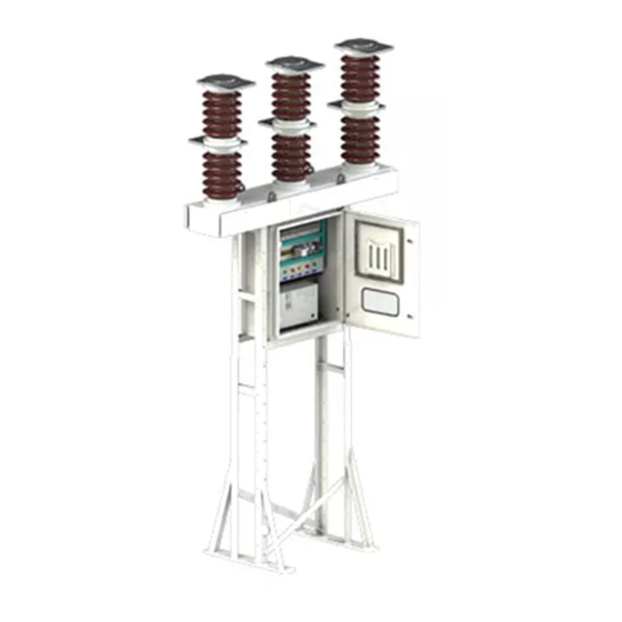
Siemens 3AF 01 vacuum circuit-breakers are of the triple-
pole outdoor type for rated voltage of 36 kV.
The vacuum circuit-breaker consists of a steel structure, a
mechanism housing complete with stored-energy spring
mechanism & control elements, and a baseframe with
three poles with vacuum interrupters mounted in
porcelain insulators and operating rods.
1.1
Standard specifications
The 3AF 01 vacuum circuit-breakers comply with the
provisions of IEC 62271-100, IEC 60694 and IS13118.
Refer Table1 for Technical Data.
Fig. 1 : Typical General Layout
NOTE
In their basic design and with all standard listed
equipment options, 3AF 01 vacuum circuit-breakers
are type-tested components in accordance with IEC.
If the customer intends to fit the breakers with
additional functions, we recommend that he should
first consult us as in most cases proven and tested
solutions are already available.
1.2
Fields of application
The combination of the special contact geometry
and contact material developed of the vacuum
interrupters enables Siemens 3AF 01 vacuum circuit-
breakers to be used universally for all fields of
application, e.g. this circuit-breaker with stored-energy
mechanism is suitable for the operating sequence
O - 0.3s - CO - 3 min. - CO.
However, certain applications, such as filter circuits,
operating reactors, furnace breakers etc., may
necessitate taking of special measures.
A. Interrupter Assembly
B. Vacuum Interrupter
C. Support Insulator
D. Base Frame
E. Top Terminal
F. Bottom Terminal
G. Drive Mechanism Housing
H. Steel Structure
J. Plexiglass for Viewing
K. Control Cable Gland Plate
L. Earthing Terminals
M. Facility for Padlock
Mechanical Indications
1
