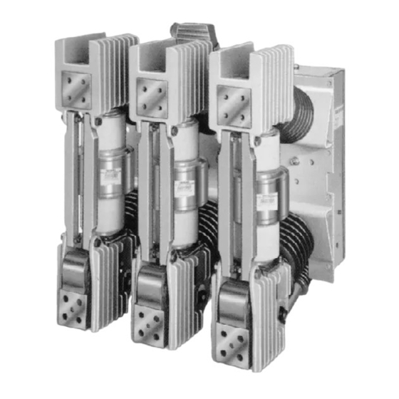
Siemens 3AH Инструкции, установка, эксплуатация, обслуживание - Страница 18
Просмотреть онлайн или скачать pdf Инструкции, установка, эксплуатация, обслуживание для Промышленное оборудование Siemens 3AH. Siemens 3AH 33 страницы. Vacuum circuit breaker operator module
Также для Siemens 3AH: Установка, эксплуатация и обслуживание (20 страниц), Руководство по эксплуатации (38 страниц)

Maintenance
Anderol 732
Beacon 325 or Supermil A-72832
Figure 13. Front View of Operator Mechanism
Lubricate all non-electrical moving or sliding surfaces with
a light coat of synthetic grease or oil. Lubricants com-
posed of diester oils and lithium thickeners will be com-
patible.
Shell (drawn cup) needle bearings:
Use either Beacon (Exxon) 325 (reference 18-658-676-
422 and part number 15-337-131-001) or Supermil
(Amoco) A-72832 (reference 18-758-676-423), or Anderol
732.
Pivots, sliding, and/or rolling surfaces and general lubri-
cation:
Use Anderol 732 aerosol synthetic fluid grease (refer-
ence part number 15-172-816-058.
Primary disconnect contacts (multi-fingered clusters on
drawout circuit breakers) and secondary disconnect contacts
(strips and fingers) are to be wiped clean, and a film of Si-
emens contact lubricant (15-171-370-002) applied. Avoid
getting contact lubricant on any insulating materials.
Fastener Check
Inspect all fasteners for tightness. Both lock-nuts and re-
taining rings are used. Replace any fasteners that appear
to have been frequently removed and replaced.
Manual Spring Charging and Contact Erosion Checks
Perform the Manual Spring Charging Check contained in
the section describing the Installation Check and Initial
Functional Tests. The key steps of this procedure are re-
peated here.
1. Insert the hand charging crank into the manual charge
socket at the front of the operator control panel. Turn
the crank clockwise (about 45 revolutions) to charge
the closing springs. Continue cranking until the
Charged flag appears in the window of the spring indi-
cator.
2. Press the Close (black) pushbutton. The contact posi-
tion indicator on the operator control panel should in-
dicate that the breaker contacts are closed.
1273-94
Figure 14. Contact Erosion Check Mark
3. Perform the contact erosion check. Contact erosion
occurs when high fault currents are interrupted or when
the vacuum interrupter is nearing the limit of its con-
tact life. Determination of acceptable contact condi-
tion is checked by the visibility of the white erosion
mark shown in Figure 14. The white erosion mark is
located in the keyway (or slot) on the movable stem of
the vacuum interrupter, near the plastic guide bush-
ing.
The contact erosion check procedure is:
a. Be sure the breaker primary contacts are Closed.
b. Observe the white erosion mark (Figure 14) of each
pole. When this mark is visible, contact wear is
within acceptable limits.
17
