Rules
You must observe the following rules when assembling a mixed configuration:
• The bus length of the ET 200SP distributed I/O system must not exceed 1 m
(without interface module, including BU-Send/BA-Send 1xFC and server module)
• A maximum of 16 ET 200AL I/O modules can be connected to ET-Connection
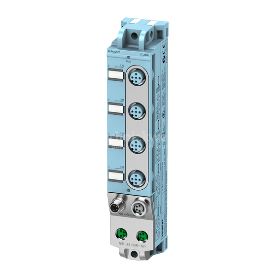
• The maximum length of the bus cable for ET-Connection between BA-Send and the first
module or between two modules is 15 m
The following table shows which firmware versions of your IM or CPU support which
maximum bus cable length.
IM/CPU
IM 155-6 PN HF
IM 155-6 PN ST
IM 155-6 DP HF
CPU 1510SP-1 PN
CPU 1510SP F-1 PN
CPU 1512SP-1 PN
CPU 1512SP F-1 PN
Procedure
To assemble a multi-tier configuration, follow these steps:
1. Switch off the supply voltage for the ET 200SP distributed I/O system.
2. Install the BaseUnit BU-Send to the immediate right of the ET 200SP CPU/interface module.
When the BaseUnit BU-Send is used next to the ET 200SP CPU, a CM DP and an Ethernet CP
or a maximum of two Ethernet CPs can be inserted between the CPU and BU-Send.
3. Then mount the additional BaseUnits / I/O modules for the ET 200SP distributed I/O system
and the server module.
4. Connect the bus cable for ET-Connection to the BusAdapter BA-Send 1xFC and install it on
the BaseUnit BU-Send.
5. Fasten the BusAdapter BA-Send 1xFC with the BaseUnit BU-Send (1 screw with tightening
torque of 0.2 Nm). To do this, use a screwdriver with a 3 to 3.5 mm blade.
6. Connect the other end of the bus cable for ET-Connection (with M8 connector) to the first
ET 200AL I/O module (X30 socket ET-Connection IN).
7. Connect the supply voltage (24 V DC) to the ET 200AL I/O modules (X80 connector).
Note
Firmware update of an ET 200AL I/O module
When you run a firmware update of an ET 200AL I/O module, ET-Connection is briefly
interrupted by the restart of the module. All downstream ET 200AL I/O modules report a
pull/plug interrupt.
Mixed configuration
Equipment Manual, 11/2020, A5E33344611-AD
Up to 10 m
V3.0 or higher
V3.1 or higher
V3.0 or higher
V2.0 or higher
Application planning
Up to 15 m
V3.3 or higher
V3.3 or higher
--
19

