Siemens SINAMICS G130 Руководство по эксплуатации - Страница 27

Просмотреть онлайн или скачать pdf Руководство по эксплуатации для Промышленное оборудование Siemens SINAMICS G130. Siemens SINAMICS G130 31 страница. Line filter
Также для Siemens SINAMICS G130: Руководство по эксплуатации (24 страниц), Руководство по эксплуатации (26 страниц), Руководство по эксплуатации (46 страниц), Руководство по эксплуатации (24 страниц), Руководство по эксплуатации (30 страниц), Руководство по эксплуатации (28 страниц), Руководство по эксплуатации (30 страниц), Руководство по эксплуатации (22 страниц), Руководство по эксплуатации (28 страниц), Руководство по эксплуатации (30 страниц), Руководство по эксплуатации (34 страниц), Руководство по эксплуатации (46 страниц), Руководство по эксплуатации (26 страниц), Руководство по эксплуатации (26 страниц), Руководство по эксплуатации (28 страниц), Руководство по эксплуатации (42 страниц), Руководство по эксплуатации (46 страниц), Руководство по эксплуатации (24 страниц), Руководство по эксплуатации (24 страниц), Руководство по эксплуатации (30 страниц), Руководство по эксплуатации (42 страниц), Руководство по эксплуатации (38 страниц), Руководство по эксплуатации (46 страниц), Руководство по эксплуатации (28 страниц), Руководство по эксплуатации (22 страниц), Руководство по эксплуатации (24 страниц)
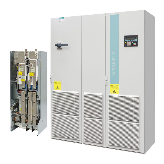
Siemens SINAMICS G130 Руководство по эксплуатации
Due to the flow of air within the cabinet, the device fan draws in pre-heated air. This heats up
the components considerably and the ventilator does not function effectively.
NOTICE
To prevent an air short circuit
Devices must not be operated in an air short circuit, since this can cause it to fail.
Suitable barriers must be in place to prevent an air short circuit.
Barriers must be installed in such a way that no air can flow along the outer sides on the top
and bottom of the devices. In particular, air must be prevented from flowing from the top
(warm discharged air) to the bottom (cold cooling air). Suitable plates can be used as
barriers. and must reach up to the side panels or cabinet doors. They must be set up in such
a way that the outgoing air current is not forced into the cabinet cross-beams but is instead
diverted around them. Barriers must be in place for all degrees of protection higher than
IP20.
The cabinets adjacent to the converter cabinets must also be taken into account when
barriers are installed.
To ensure sufficient ventilation for the devices, the opening cross-sections (minimum values)
specified in the following table must be observed.
The specified opening cross-sections comprise several small openings. To ensure that
pressure loss is kept to a minimum and that the flow resistance does not become too great
at these mesh-type openings, the cross sectional area of each opening must be around at
least 190 mm² (e.g. 7.5 mm x 25 mm or 9.5 mm x 20 mm).
To ensure that the devices operate continuously, suitable measures must be taken to
prevent the ingress of dirt and dust. Wire lattices (wire fabric DIN 4189-St-vzk-1x0.28) or
filter mats (min. filter class G2) must be used for this purpose. The choice of filter mats
depends on the required degree of protection and the ambient conditions. If cabinets are
installed in an environment containing fine dust particles or oil vapors, micro-filter mats must
be used to prevent the devices from becoming contaminated.
If dirt filters are used, the specified opening cross-sections and the filter areas must be
adjusted upwards.
NOTICE
Note dirt filter replacement intervals
If dirt filters are used, the specified replacement intervals must be observed.
If the filter mats are heavily contaminated, the volume of air drawn is reduced due to the
increased flow resistance. This can cause the fans integrated in the devices to overload, or it
could cause the devices themselves to overheat and become damaged.
Cabinet design and EMC
Operating Instructions, 03/2013, A5E00427629A
Cabinet air conditioning
5.2 Ventilation
25