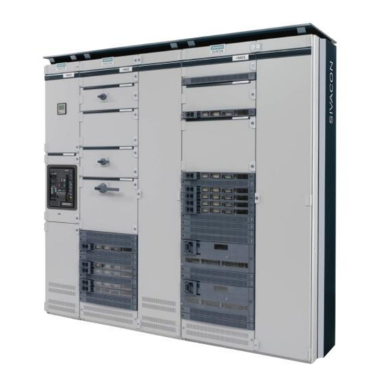
Siemens SIVACON S 8PQ Series Руководство по эксплуатации - Страница 39
Просмотреть онлайн или скачать pdf Руководство по эксплуатации для Промышленное оборудование Siemens SIVACON S 8PQ Series. Siemens SIVACON S 8PQ Series 40 страниц. Design-verified low-voltage switchboard
Также для Siemens SIVACON S 8PQ Series: Руководство по эксплуатации (11 страниц)

- 1. Table of Contents
- 2. Sivacon Bauartgeprüfte Niederspannungsschaltanlage S8 - Felder mit Abzweigen in Einschubtechnik Design-Verified Low-Voltage Switchboard S8- Cubicles with Feeders in Withdrawable Design Betriebsanleitung / Operating Instructions Bestell-Nr. / Order No.: 8P
- 3. Description of the MCC Cubicle
- 4. Electrical Connections
4.4.2.4 Fach bei Anschluss in Anlage von hinten
Anschlussterminals und Trennwände ein- und ausbauen
Ausbau:
Vor dem Ausbau ist der entsprechende Einschub aus dem
Fach zu entnehmen sowie Haupt- und Steuerleitungen abzu-
klemmen.
Befestigungsschrauben (Torx 30) für das Tragblech der Steuer-
leitungsbuchse (a) und des Abgangsgehäuses (b) im Fach ent-
fernen [Abb.A]
Lösen der Schrauben und des Trennbleches zum Kabelan-
schlussraum (c), sowie der Befestigungsschrauben des Ab-
gangsgehäuses (d) und des kleinen Trennbleches (e) [Abb.B]
und entfernen der Trennbleche [Abb.C]
A
b
b
Trägerblech der Steuerleitungsbuchse ca. 20mm nach vorn
ziehen, so dass es im hinteren Bereich vor dem Abgangsge-
häuse zu liegen kommt [Abb. D]
Abgangsgehäuse nach links schieben [1], nach hinten bewegen
[2] und nach oben [3] aus der Verankerung im Fachboden lösen
und heraus nehmen [Abb. E].
D
Falls die Steuerleitungen auch getauscht werden, Blechkanal (f)
im Kabelanschlussraum abschrauben, Klemmblock von Hut-
schiene abnehmen und komplette Steuerverdrahtung mit Trag-
blech der Steuerleitungsbuchse herausnehmen
Einbau:
Beschriebene Schritte in umgekehrter Reihenfolge und Rich-
tung durchführen, Furchschrauben M6 (Torx 30/ 4Nm) befesti-
gen.
Der Einbau ist auf Zeichnung 8PQ5000-0AA67 dargestellt, für
100mm hohe Fächer siehe Zeichnung 8PQ5000-3AA35.
8PQ9800-3AA48
a
a
F
f
4.4.2.4 Compartment for rear connection
Fitting and removing terminals and partitions
Removal:
Before removal, the corresponding withdrawable unit must be
removed from the compartment as well as clamping main and
control cables.
Remove fixing screws (torx 30) of the supporting plate for
control cables (a) and the outgoing feeder housing (b) [fig. A]
Unscrew the fixings screws for the separating plates to the
cable compartment (c), the screws for the outgoing feeder
housing (d) and the small separating plate (e), remove the sep-
arating plates [fig. C]
B
c
d
e
pull the supporting plate for control cables approx. 20mm to the
front to release the outgoing feeder housing [fig. D]
move outgoing feeder housing to the left [1], backwards [2] and
lift it up [3] to remove the outgoing feeder housing [fig. E]
E
3
if the control cables have to be changed, unscrew the cable
channel in the cable connection compartment (f), release the
cable connection terminals from DIN rail and take out the con-
trol cables including the supporting plate and terminals
Installation:
Follow the instruction beginning from the end in the opposite
sequence an direction and fix with the thread-forming screws
M6 (torx 30 / 4 Nm).
The Installation is shown on the drawing 8PQ5000-1AA67, for
100mm high compartments refer to drawing 8PQ5000-3AA35.
c
C
1
2
37
