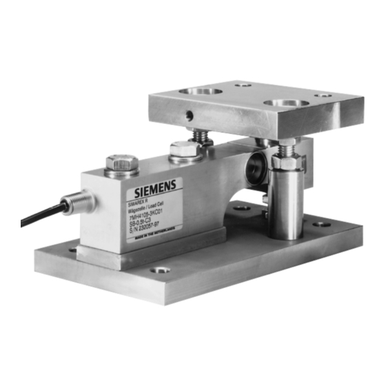
Siemens SIWAREX R Руководство по эксплуатации - Страница 13
Просмотреть онлайн или скачать pdf Руководство по эксплуатации для Промышленное оборудование Siemens SIWAREX R. Siemens SIWAREX R 38 страниц. Mounting units for sb series
Также для Siemens SIWAREX R: Руководство по эксплуатации (34 страниц)

Revision 09/04
2. Mounting point height adjustment
The output signals of all load cells are determined one after the other when they
are loaded. In order to achieve similar load on all of them, spacer plates are used to
adjust the height. The spacer plates are pushed in between the brackets and the top
plate of the mounting element for the best results.
The output signals of the individual load cells correspond to load distribution.
Proceed as follows to measure the output signals:
Disconnect load cell lines SIG+ and SIG-.
•
Supply the load cells with the supply voltage (e.g. 10.2V).
•
Measure the output voltage between SIG+ and SIG- on each individual load
cell.
•
Now put spacer plates under the brackets for the load cell with the lowest
value until the output voltages match.
The load cell seat must be horizontal, level over the full-coverage and like the load
cell underside, absolutely clean.
The contact surface that introduces the force is to be coated with high-performance
grease.
1.9
Dismantling
When dismantling the load cells, the same safety and security measures are to be
followed as for the installation and assembly.
•
All power supply lines are to be switched off.
•
Secure the load platform from falling.
•
User appropriate lifting mechanisms and tools.
•
Take all load off of the load cells and carefully remove them without any
excessive force (no jolting movements).
•
Do not cut the cable if the load cells are to be used again or if being sent in
for repair.
•
To not step on or pull on the cable for moving the load cells.
1.10 Explosion Protection
There is no danger of explosion caused by the mounting elements of the load cells
and therefore they are not subject to the EC Directive 94/9 EG (ATEX).
Document No.: A5E00353789B
General Conditions for Installation and Assembly
Page 13
