Siemens SIWAREX R Руководство по эксплуатации - Страница 8
Просмотреть онлайн или скачать pdf Руководство по эксплуатации для Промышленное оборудование Siemens SIWAREX R. Siemens SIWAREX R 38 страниц. Mounting units for sb series
Также для Siemens SIWAREX R: Руководство по эксплуатации (34 страниц)

Revision 09/04
the permitted movement, on all sides, cannot be exceeded. In Fig. 1-2, this is
displayed in two examples.
Limit stop
Limit stop
Platform
Platform
Oscillation limitations at a permitted oscillation of 4 mm in a dual weighing
platform example.
Fig. 1-2 Oscillation limitation example
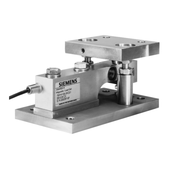
Load cells of the SB series have oscillation limitations integrated in them with the
combination mounting units.
CAUTION
When using weighing cells with low rated loads, overload protection are to be
used, cross-directional as well, in order to protect the cells from damage.
The use of load cells above the maximum working load or the maximum lateral
load can lead to irreparable faults or damage to the load cells or the mounting unit.
1.3
Guidings
Guidings compensate for cross-forces immediately. They allow no sideways
movement of the load platform. At the same time, they cannot change shape when
distances change in the support points (e.g. thermal expansion). Guiding
positioning is shown in Fig. 1-3. They are used if the weight must be determined
under the influence of a transverse force.
Guidings must be constructed perpendicular to the effective direction of the load
cells so that there are no force components in the direction of measurement.
Stretching the guidings is best avoided when they are positioned with the same
direction of rotation. To fasten a loading platform or a hopper in a static position,
three guidings will suffice. With four guidings, there is a danger of these putting
force on each other and that this could cause weighing errors. If four guidings are
used anyway, they should be installed with enough play to compensate.
Document No.: A5E00353789B
General Conditions for Installation and Assembly
2.8
2.8
2.8
Drill hole
Drill hole
Bolt
Bolt
±2.8
±2.8
±2.8
Platform
Platform
4
4
±4
±4
Page 8
