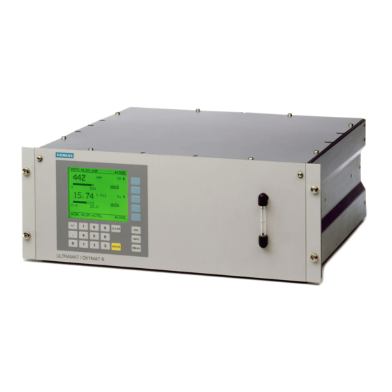
Siemens ULTRAMAT 6F Руководство по технике безопасности - Страница 10
Просмотреть онлайн или скачать pdf Руководство по технике безопасности для Промышленное оборудование Siemens ULTRAMAT 6F. Siemens ULTRAMAT 6F 24 страницы. Gas analyzer for the determination of ir-absorbing gases
Также для Siemens ULTRAMAT 6F: Руководство по дополнительному оборудованию (20 страниц), Руководство по эксплуатации (49 страниц)

Siemens AG
2.2
Safety Integrity Level (SIL)
Definition: SIL
The international standard IEC 61508 defines four discrete Safety Integrity
Levels (SIL) from SIL 1 to SIL 4. Each level corresponds to the probability
range for the failure in a safety function. The higher the SIL of the safety-
instrumented system, the higher the probability that the required safety
function will work.
The achievable SIL is determined by the following safety characteristics:
•
•
•
Description
The following table shows the dependency of the SIL on the average
probability of dangerous failures of a safety function of the entire safety-
instrumented system (PFD
i.e. the safety function is required a maximum of once per year on average.
SIL
4
3
2
1
Table 2-1 Safety Integrity Level
The "average probability of dangerous failures of the entire safety
instrumented system" (PFD
subsystems in the following figure.
Sensor
e.g. Gas
Analyzer
Figure 2-2 PFD distribution
The following table shows the achievable Safety Integrity Level (SIL) for
the entire safety-instrumented system for type B systems depending on
the proportion of safe failures (SFF) and the hardware fault tolerance
(HFT). Type B systems include sensors and positioners actuators with
complex components, e.g. microprocessors (see also IEC 61508, Section
2).
60 to 90%
90 to 99%
SIL Safety Manual ULTRAMAT 6 Gas analyzers
A5E00729183-02
Average probability of dangerous failure of a safety function in case
of demand (PFD
AVG
Hardware fault tolerance (HFT)
Safe failure fraction (SFF)
PFD
AVG
≥ 10
... < 10
-5
-4
≥ 10
... < 10
-4
-3
≥ 10
... < 10
-3
-2
≥ 10
... < 10
-2
-1
SFF
0
<60%
Not allowed
SIL1
SIL2
>99%
SIL3
)
). The table deals with "Low demand mode",
AVG
) is normally spilt between the three
AVG
Control
system or
logic unit
e.g. PLC
HFT
1
SIL1
SIL2
SIL3
SIL4
8 of 19
Final control-
ling element
e.g. Valve
2
SIL2
SIL3
SIL4
SIL4
