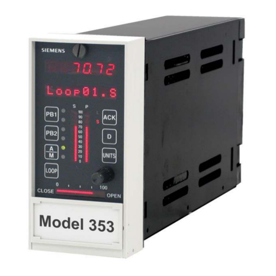
Siemens 353 Руководство пользователя - Страница 17
Просмотреть онлайн или скачать pdf Руководство пользователя для Контроллер Siemens 353. Siemens 353 20 страниц. Multi-purpose training panel
Также для Siemens 353: Руководство пользователя (4 страниц)

UM353TP-1
3.0 OPERATION
This section describes the Multi-Purpose Training Panel's controls and displays.
The Training Panel can provide all I/O signals needed to configure and operate a Model 353 controller with or
without the use of external process control devices. The controls, binding posts, and displays on the front of the
Training Panel and the Ethernet connector at the back of the case provide access to the following signals:
•
Analog inputs to AIN1, AIN2, AIN3, and AIN4
•
Analog outputs from AOUT1, AOUT2, and AOUT3
•
Digital inputs to DIN1, DIN2, DIN3, and DIN4
•
Digital outputs from DOUT1 and DOUT2
•
Relay contact outputs from ROUT1 and ROUT2
•
Universal analog inputs to AUIN1 and AUIN2
•
Universal digital inputs to DINU1 and DINU2
•
Modbus communication
•
Local Instrument Link (LIL) communication
•
Ethernet communication
•
LonWorks communication
For information about configuration procedures, function blocks, and operating procedures, refer to the
Configuration Overview, Function Blocks, and Operation sections of the Model 353 User's Manual, UM353-1.
Refer to Figure 3-1 for the location of Training Panel controls described in the following sections. Figure 3-2
presents a wiring diagram of the Training Panel with controller Case Option 2. Wiring of a Training Panel with
Controller Case Option 4 is similar with the addition of an Ethernet connector and cable (see Figure 2-2).
3.1 ANALOG INPUTS
The analog input signal to AIN1, AIN2, AIN3, or AIN4 is selected using a three-
position switch located on the right side of the Panel. An I/O Expander board
must be installed in the controller to activate Analog Input 4 (AIN4).
Select the desired input signal source as follows.
•
Switch thrown to right (as shown at right) - The +6 Vdc signal from the
Training Panel becomes the input source. The input signal level is
controlled by the adjacent potentiometer.
•
Switch in the center position - The analog output from the associated AOUT
function block becomes the input to the function block. AIN4 does not have
an associated AOUT.
•
Switch thrown to left - The input signal is supplied by an external voltage
source connected to the adjacent binding post. The source can be a field
device, such as a two-wire transmitter, or an output from one of the Panel's
AOUT binding posts. For example, use a jumper wire to connect AOUT3 to
the binding post for AIN1.
In the wiring diagram, Figure 3-2, the four switches are identified as SW1
through SW4.
April 2002
Operation
SIMULATED ANALOG INPUTS
AIN1
AIN
AOUT1
AIN
AIN2
AOUT2
AIN
AOUT3
AIN3
NC
AIN4
AIN
Four, three-position switches to
select the analog input sources.
3-1
