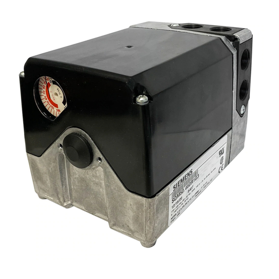
Siemens SQM56.667R1G7R Технические инструкции - Страница 22
Просмотреть онлайн или скачать pdf Технические инструкции для Контроллер Siemens SQM56.667R1G7R. Siemens SQM56.667R1G7R 31 страница. Reversing
Также для Siemens SQM56.667R1G7R: Технические инструкции (31 страниц), Технические инструкции (31 страниц)

Technical Instructions
Document No. 155-517P25
July 9, 2007
AGA56.41/42/43
Circuit Board
Installation, Continued
AGA56.9A...
Circuit Board
Installation
Page 22
8. Make the following connections to the
actuator: See Figure 22.
a. Connect the wire, marked "1" from
the circuit board to switch I,
terminal 1.
b. Connect the wire, marked "2" from
the circuit board to switch II,
terminal 2.
c. Connect the wire, marked "3" from
the circuit board to switch III,
terminal 3.
d. Connect the wire, marked "13"
from the circuit board to switch III,
terminal 13.
e. Connect the blue neutral wire
marked "N" to the double terminal
block located on the outer end of
the switch housing
f.
Connect the grounding wire
marked "51" to the ground terminal
located to the right of the
auto/manual switch.
1. Remove the ASZ... potentiometer if
already installed on the SQM5...
actuator. See Potentiometer
Removal/Installation Instructions.
2. Remove the AGA56.9A... circuit
boards from the packaging. The three
separate AGA56.9A circuit boards are
shipped in a circuit board mounting
bracket.
3. Remove the two upright circuit boards
from the mounting bracket by gently
pulling aside the vertical supports and
sliding the boards upward. Remove
the base circuit board from the bottom
of the mounting bracket. Discard the
shipping mounting bracket.
SQM5... Reversing Actuators
18
17
16
15
14
13
12
11
28
27
26
25
24
23
22
21
8
7
6
5
4
3
2
1
VIII
VII
VI
V
IV
III
II
I
N
TERMINAL
BLOCK
MAN.
0
AUTO
N
Figure 22.
Siemens Building Technologies, Inc.
13
3
2
1
