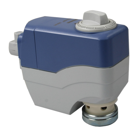
Siemens SSC31 Руководство - Страница 4
Просмотреть онлайн или скачать pdf Руководство для Контроллер Siemens SSC31. Siemens SSC31 9 страниц. Electromotoric actuators
Также для Siemens SSC31: Руководство (8 страниц)

Notes
Engineering
Caution
Mounting
Orientation
Commissioning
Caution
Operation
Note
4/8
Siemens Building Technologies
HVAC Products
The actuators must be electrically connected in accordance with local regulations (refer
to «Connection diagrams»).
Regulations and requirements to ensure the safety of people and property must
be observed at all times!
The permissible temperatures must be observed (refer to «Technical data»).
Mounting Instructions 74 319 0260 0 are enclosed with each pack.
Assembly is made with the coupling nut; no tools or adjustments are required. The
actuators should be installed so that they are initially in position 0 (also refer to
«Operation»).
90°
90°
When commissioning the system, check wiring and the functions of the actuator.
Before testing the functioning of the SSC..., always check to ensure that the
actuator concerned is mounted on a valve (refer to «Equipment combinations»).
Calibrating the SSC61 or SSC61.5 without a valve connected causes the actuator to
lock in position 1. To recalibrate (after mounting on a valve), disconnect power and
reset the stroke manually from position 1 to 0 (refer to «Recalibration»).
The rotary knob can be used to drive the actuator into any position between 0 and 1.
However, if a control signal from the controller is present, this will take priority in
determining the position.
To retain the manually set position, unplug the connecting cable. Due to the reset
function, the SSC61.5 will first travel to position 0 and can then be driven manually to the
required position.
A
A
B
(Y, Y1)
Electrical Actuators
A
B
1
(Y2)
Position indicator in
position 1 = OPEN
B
0
Position indicator in
position 0 = CLOSED
CA1N4895en
08.03.2004
