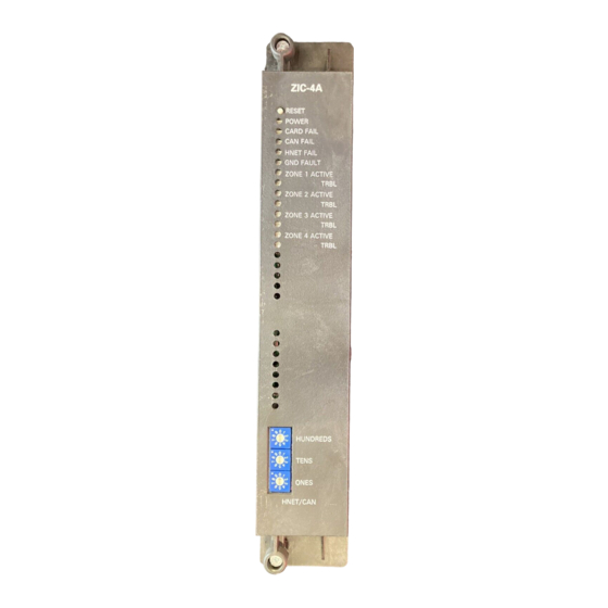
Siemens ZIC-4A Руководство по установке - Страница 18
Просмотреть онлайн или скачать pdf Руководство по установке для Блок управления Siemens ZIC-4A. Siemens ZIC-4A 24 страницы. Zone indicating card

NOTES
1. All wiring must be in accordance with
Article 760 of NEC or local building
codes. Wiring for each zone can
either be Class A or Class B.
2. All output circuits are power limited
to NFPA 70 per NEC 760.
3. Electrical Ratings:
Output Zone Supervisory:
4mA max
Output Zone Active:
96 Watts max / zone
4. EOL resistor, 24k ohms,
1 watt , 5%, P/N 140-033771.
5. Polarity shown in active state.
6. For a list of Compatible Notification
Appliances, refer to P/N 315-096363.
7 . Refer to CAB1/CAB1R (P/N 315-
0330007) and CAB2-BB/CAB3-BB (P/
N 315-033009) Installation Instruc-
tions for details on the separation of
power limited and non-power limited
wiring.
8. Positive or negative ground fault
detected at <40K ohms for
terminals 1-16.
STYLE Z
(CLASS A)
TO NEXT ZIC-4A
Figure 13
ZIC-4A Single-Channel Audio Wiring
Siemens Industry, Inc.
Building Technologies Division
ZONE 1
STYLE Z
CLASS A
24K,
1W
5%
1
2
3
ZONE 3
9
10
11
24K,
1W
5%
ONE SLOT OF CC-5
17
18
19
18
ZONE 2
24K,
STYLE Y
1W
CLASS B
5%
NC
NC
4
5
6
7
8
12
13
14
15
16
NC
NC
20
21
22
23
24
STYLE Y
ZONE 4
(CLASS B)
24K,
1W
5%
AUDIO FROM PREVIOUS
ZIC-4A OR FROM
ZAC-40/
ZAM-180 TERMINALS
1A AND 1B OR 2A AND 2B
P/N 315-033050-15
