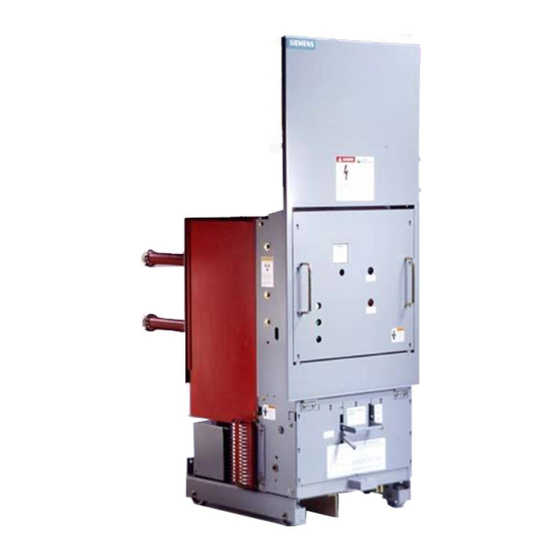
Siemens 15-FSV-1000 Установка, эксплуатация и обслуживание - Страница 31
Просмотреть онлайн или скачать pdf Установка, эксплуатация и обслуживание для Переключатель Siemens 15-FSV-1000. Siemens 15-FSV-1000 48 страниц. Vacuum circuit breakers fsv series and msv series

Interrupter/Operator
Maintenance
1 00,000
:
<J)
c
0
cil
w
Q_
0
�
1 00 1
0
Q,
<J)
0
u
0
w
.D
E
:::J
z
Breaking Current (Amps)
a - 5-MSV-250
b
5-FSV-350
d - 1 5-FSV-500
-
c
- 7 -FSV-500
e - 1 5-FSV-750
Figure 19
Typical Primary Interrupter Contact Life Curve
Interrupter Vacuum Check Mechanical
(Ref. figs. 2 1 a , 2 1 b ,
2 1 c
&
Before putting t h e breaker into service, o r i f a n i n terrupter i s
suspected o f leaking as a result o f mechanical damag e , check
the vacuum either mechanically as described i n this section
or alternatively electrically using a high potential test set as
described i n the next secti o n .
O p e n and isolate the breaker and detach the insulated cou
pler, 48 , from lever, 4 8 . 6 , Fig . 2 1 a.
The atmospheric pressu re w i l l force the moving contact of a
hermetically sealed interru pter i nto the " C losed" position,
causing lever, 4 8 . 6 , to move i nto the position shown i n Fig . 21 b .
A vacuum interrupter m a y be assumed to be intact if it shows
the following characteri stics:
An appreciable closing force has to be overcome when leve r,
4 8 . 6 , is moved to the " O P E N " position by hand, F i g . 2 1 c . When
the lever is released , it must automatically return to the
"CLOSED" position with an audible sound as the contacts touch.
After checking the vacu u m , reconnect the lever, 4 8 . 6 , to the
i n s u l ated cou p l e r 48.
High Potential Testing and Electrical Interrupter Vacuum
Check
H i g h Potential tests are p e rformed to affirm the breakers di
electric i nteg rity, and to establish by alternate means of check
ing the i n terrupters vacu u m .
T h e primary i n s u l ation system o f t h e c i rcuit b reaker may b e
checked by c l o s i n g the b reaker, and a p p lying t h e voltag es
l i sted below between a primary conductor of each pole and
g round .
Prior to applying the test voltag e , each pole not under test
shall be g rounded. Apply test voltage for one m i nute. I f no
d i s r u ptive d i scharge occurs which permanently reduces the
test voltage to zero, the primary insu lation system is acceptab le.
I n terrupter vacu u m may be checke d by apply i ng the test volt
ages l i sted below across each i nterrupter with the breaker
ac
d
b
f
e
f -
1 5-FSV-1 000
Figure 20
Contact Erosion Check
Strut
28
29 . 1
Flexi b l e Connector
Vac u u m i nterrupter
30.
Page 26
28
30
A
29. 1
40
40.
Lower pole sup port
A
Check mark
