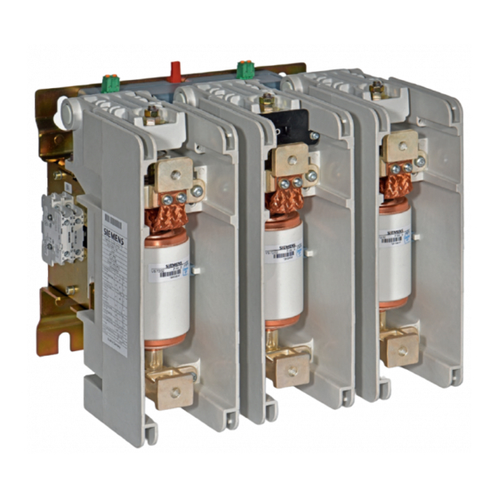
Siemens 3TM Руководство по эксплуатации - Страница 30
Просмотреть онлайн или скачать pdf Руководство по эксплуатации для Переключатель Siemens 3TM. Siemens 3TM 48 страниц. 1-pole vacuum contactor 4.15 kv - 6.9 kv

Installation
Removing the side plate
Fig. 28
Removing the side plate
Mounting the side plate
Wiring the connectors for
the electronic controller
30
•
Remove the screws on the side plate (33) and remove the side plate (see
Fig. 28).
23
Auxiliary switch
33
Side plate
44
Switching lever cam
45
Switching lever for auxiliary switch
*
Recess in switching lever
•
Connect the auxiliary switch (23) in accordance with the circuit diagram.
•
If present, remove the label from the switching lever (45)
•
Insert a screwdriver in the recess (*) in the switching lever (45) for the auxiliary
switch (23).
•
Position the side plate (33) and move the switching lever (45) with the screw-
driver so that the switching lever (45) fits easily in the opening in the cam (44)
(see Fig. 29).
•
Securely screw on the side plate (33).
•
The correct position is achieved when the switching lever (45) can only be
moved slightly back and forth.
If the switching lever (45) can be moved far in one direction after installation, the
switching lever (45) is not inserted in the cam (44) and the above steps must be re-
peated.
The electronic controller (24) for the vacuum contactor is the interface to the custom-
er-side connection. Protection with appropriate fuses is performed by the customer.
Use the respective 2-pole plug or screw connectors supplied in the accessory pack
according to the supplied circuit diagram.
Note
Connectors for A1/A2 and E1/E2 can become loose through repeated
disconnection.
When installing a new vacuum contactor, use only the new connectors provided
in the accessory pack and rewire.
To protect against the effects of oscillations and vibrations, the connectors are wired
(see also Fig. 30 and Fig. 31):
•
without shear, tensile, or compressive stresses
Fig. 29
Mounting the side plate
9229 0098 176 0-
2019-01-09
