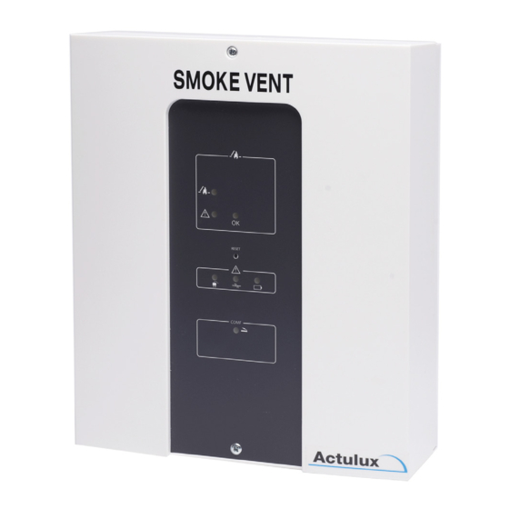
Actulux SVM 24V-8A Руководство пользователя и инструкция по установке - Страница 9
Просмотреть онлайн или скачать pdf Руководство пользователя и инструкция по установке для Панель управления Actulux SVM 24V-8A. Actulux SVM 24V-8A 11 страниц. For fire ventilation

- 1. Table of Contents
- 2. General Description
- 3. Safety Rules During Installation and Operation
- 4. Explosion Danger
- 5. Installation
- 6. Yearly Legal Requirement of Maintenance and Control
- 7. Connection to Motor- (Actuator) Outputs and Line Monitoring
- 8. Current Limiter Type LIP
- 9. Connection of Smoke-/Heat Detectors
- 10. Comfort Ventilation - Connection and Settings
- 11. Fuse Specifications
- 12. Connection of Weather Sensor / Close All Function
- 13. Special Functions
- 14. Cable Sizes
- 15. Part Nos. and Accessories
- 16. Technical Specifications
Control for Fire and Comfort Ventilation Type SVM 24V-5A / SVM 24V-8A
Special functions
Sprinkler function:
DIP 9 On - a special function comes in use where sprinkler systems are installed. With this function
activated, the actuator output closes, if smoke-/heat detector input is activated.
If the fire switch is activated, the actuator output opens.
Weekly open/close:
DIP 7 On - the motor output opens shortly (3 seconds) once a week and closes immediately after -
This function is used to give the right tension on the packing of the skylights to keep them watertight.
Function of heat detector in LIP:
DIP 3 On - a heat detector 70-100° can be mounted in each LIP. If the temperatur is exceeded, the
control panel goes into alarm and the opening system is opening.
Special mode:
DIP 12 On - possible to use comfort switch also during line fault, low batt., no AC, Alarm only as long
as fire input is active or detector is activated.
Cable sizes
It is very important to use the correct cable types and sizes to make sure that the fire ventilation system
meets the standards and works correct in an emergency.
The two most important factors are the ability of the cables to resist heat and to make sure that the
voltage drop in the cables to the actuators do not exceed 15% at full load on the fire ventilation hatches.
Fire resistant cables according to IEC 60331 must be used for the following functions:
Opening systems with actuators 24V 2 wires, see diagramme (3 wires by external line surveillance)
Fire switch 24V
Min. 6 x 0,5 mm²
Smoke detector 24V
Min. 2 x 0,5 mm²
Heat detector
Min. 2 x 0,5 mm²
Cable between control panels (bus)
3 x 0,5 mm²
Normal cables can be used for the following functions:
Supply for control 230VAC
e.g. 3 x 1,5 mm² PVIK-J
Comfort ventilation button 24V
Min. 3 x 0,5 mm²
Wind- and rain sensor 24V
Min. 4 x 0,5 mm²
16
Control for Fire and Comfort Ventilation Type SVM 24V-5A / SVM 24V-8A
Table for SVM 24V-5A/8A allowed voltage drop 15% = 3,6V
Cable cross section and amount of cores
Power
consumption
per group in
2x1,5 mm²
2x2,5 mm
4x1,5 mm
²
ampere
(2x1,5+2x1,5)
2
74 m
123 m
148 m
4
37 m
61 m
74 m
6
25 m
41 m
50 m
8
18 m
31 m
36 m
4x2,5 mm
2x6 mm
5x2,5 mm
2x10 mm
²
²
²
²
(2x2,5+2x2,5)
(2x2,5+3x2,5)
246 m
295 m
307 m
292 m
122 m
148 m
154 m
244 m
82 m
98 m
102 m
164 m
62 m
74 m
77 m
124 m
17
²
