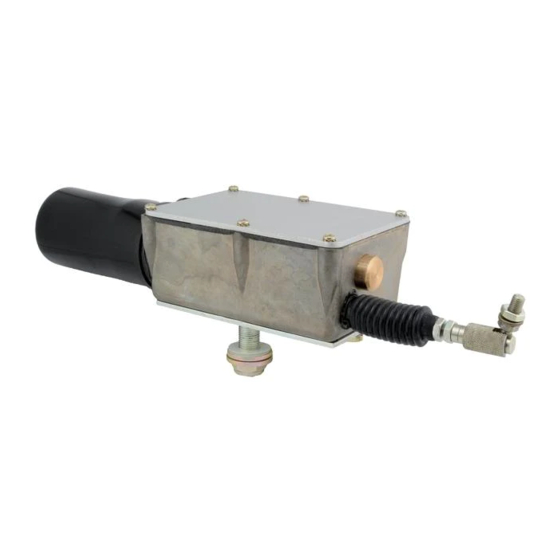
ACTUS 720 Series Базовая настройка
Просмотреть онлайн или скачать pdf Базовая настройка для Контроллер ACTUS 720 Series. ACTUS 720 Series 7 страниц.

720 SERIES ACTUATOR – BASIC SETUP
1. Complete the wiring of the electrical system per the enclosed wiring
diagram (Actus drawing number 999-0172). Note the 3 Amp (slow
blow) breaker in the circuit. This is highly recommended as a standard
practice to protect the actuator from overload and failure. A slow blow
fuse is required because draw can reach 7 amps when stalled.
2. Before applying power, double check the following important areas:
a. Proper wiring technique is critical. All wires and cables should be
tied down and positioned so they will not be accidentally pulled
or knocked loose. All wiring subject to high wear or vibration
should be run through loom to protect from shorting to the
vehicle frame.
b. Double check all ground wires as shown on the wiring diagram.
All frame grounds should be free of corrosion, paint, and dirt.
Wires shown running direct to the negative post of the battery
should be attached there, or to a similar good direct ground.
Frame grounding is not recommended for these wires. Note that
this actuator is grounded with terminal #3. Terminals #4 and
#5 provide bi-directional motor control.
c. This is a negative ground, 12 or 24 VDC system. Be sure correct
power is applied and regulated.
d. Certain motor speeds require different wiring. Check the truth
table on the wiring diagram.
3. Mount actuator to device that is to be stroked. Check to make sure
mounting mechanism on the actuator matches mounting required to
stroke the lever. This is a linear actuator and will be damaged if it is
stroking a mechanism that is not moving in a straight linear motion.
This arcing motion requires the actuator to be mounted with the pivot
pin mounting bracket option. Also be sure to minimize side loads to
the actuator rod end.
090407AJN
