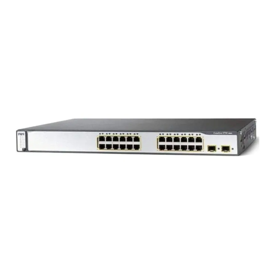
Cisco 3750G - Catalyst Integrated Wireless LAN Controller Руководство по началу работы - Страница 17
Просмотреть онлайн или скачать pdf Руководство по началу работы для Сетевое оборудование Cisco 3750G - Catalyst Integrated Wireless LAN Controller. Cisco 3750G - Catalyst Integrated Wireless LAN Controller 49 страниц. Integrated wireless lan controller switch
Также для Cisco 3750G - Catalyst Integrated Wireless LAN Controller: Руководство по конфигурации (40 страниц)

Enter the IP addresses of the primary and the optional secondary DHCP servers that
Step 21
supply IP addresses to the controller AP-manager interface. If the AP-manager interface is
on the same subnet as the management interface, the AP-manager interface uses the same
DHCP server IP address as the management interface.
Click Next. The Virtual Interface Configuration page appears.
Step 22
In the IP Address field, enter the IP address of the controller virtual interface to be used
Step 23
by all controller Layer 3 security and mobility managers. You should enter a fictitious,
unassigned IP address, such as 1.1.1.1.
The virtual interface is used to support mobility management, DHCP relay, and embedded
Layer 3 security such as guest web authentication and VPN termination. All controllers
within a mobility group must be configured with the same virtual interface IP address.
In the DNS Host Name field, enter the DNS host name if your controller uses an externally
Step 24
generated web authentication ID certificate that includes a DNS hostname.
17
