Digitrax DN163I1A Руководство - Страница 3
Просмотреть онлайн или скачать pdf Руководство для Медиаконвертер Digitrax DN163I1A. Digitrax DN163I1A 9 страниц.

5. Solder headlight
leads to the new
decoder board as
shown If you were
sitting in the cab,
the yellow lead
would be on your
left and the green
lead would be on
your right. The final
step is to secure the
decoder with the
original screws.
Note: the locomo-
tive's frame halves
may have to be
loosened slightly to
achieve proper
alignment.
CAUTION: When attaching headlight wires, be very careful that the wires
you attach do not come into contact with any other pads or components on
the board where they might create a short circuit.
Installation Notes:
1. Do not exceed the decoder's 500mA total function output rating.
2. To use a function output with an inductive (coil) type load, see the Digitrax
Decoder Manual for more information to avoid damage to the decoder.
3. See the Digitrax Decoder Manual for full details of wiring 12-16V lamps,
1.5V lamps, and LEDs. Lamps that draw more than 80 mA when running
require a 22 ohm 1/4 watt resistor in series with the directional light func-
tion lead to protect the decoder.
C C u u s s t t o o m m i i z z i i n n g g Y Y o o u u r r D D e e c c o o d d e e r r
Your Digitrax decoder is ready to run and will operate using address 03 with no
additional programming. For a more prototypical railroading experience, your
decoder can be customized for your specific locomotive by programming some
of the Configuration Variables, or CVs, available. See the Digitrax Decoder
Manual or the Digitrax web site for more information.
C C h h a a n n g g i i n n g g t t h h e e D D e e c c o o d d e e r r A A d d d d r r e e s s s s
The first CV most people change is the decoder address so that the loco can be
independently controlled with it's own unique address. All Digitrax decoders
©2004 Digitrax, Inc
4 4 5 5 0 0 C C e e m m e e t t e e r r y y S S t t r r e e e e t t
N N o o r r c c r r o o s s s s , , G G A A U U S S A A 3 3 0 0 0 0 7 7 1 1
w w w w w w . . d d i i g g i i t t r r a a x x . . c c o o m m
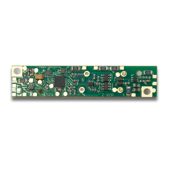
Figure 4: Solder headlight
wires, secure new decoder
with original screws
www.digitrax.com
7 7 7 7 0 0 - - 4 4 4 4 1 1 - - 7 7 9 9 9 9 2 2
T T
7 7 7 7 0 0 - - 4 4 4 4 1 1 - - 0 0 7 7 5 5 9 9
F F
s s a a l l e e s s @ @ d d i i g g i i t t r r a a x x . . c c o o m m
E E
Yellow wire
Green wire
3
