Digitrax TSMK Руководство - Страница 2
Просмотреть онлайн или скачать pdf Руководство для Блок управления Digitrax TSMK. Digitrax TSMK 4 страницы. Terminal strip mounting kit-all scales

Hooking Up Your Signal Masts
You can use the Terminal Strip Mounting Kit for connecting any signal mast in
any scale to the Signal Driver Cable.
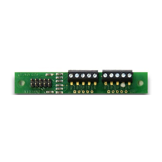
1. Attach the wires from the signal heads to the TSMK as shown below. The
circuit board is labeled to make it easy to see where to hook up the wires.
2. Insert the wires from the signal heads into the screw terminals according to
the diagram below. Use a small screwdriver to close the screw terminal
(Rotate the screwdriver clockwise to close and counter-clockwise to open
the screw terminals).
3. The TSMK provides the resistors required for connecting the LEDs on the
signal mast.
For clarity, the following examples use a line name for each Terminal Strip
Mounting Kit screw terminal to avoid confusion with wire colors. In the
first example, 3/3 Signal heads with green, yellow and red LEDs, the line
names correspond to the LED colors. One Terminal Strip Mounting Kit
Board must be used for the A 1 /A 2 signal heads (A Orientation) and one for
the B and C signal heads (B/C Orientation). See figure Sample Layout
Security Element (Plant)--for a typical signal location.
Signal Head Examples:
3 over 3 dual "G" type signal heads such as the Tomar H-866, can be con-
nected to a Terminal Strip Mounting Kit board. The white common anode lead
(for both heads) connects to Common Lo (Pin 1) screw terminal and the sig-
nal's longer wires from the red/green/yellow LEDs from the Lower (dwarf) sig-
nal head connect to Red Lo (Pin 7), Green Lo (Pin 3) and Yellow Lo (Pin 5)
screw terminals on the front of the Terminal Strip Mounting Kit board. The
shorter 3 wires from the upper head also connect to their respective screw ter-
minals on the Terminal Strip Mounting Kit board Red Hi (Pin 4), Yellow Hi
(Pin 6) and Green Hi (Pin 8).
Single signal heads such as Tomar H-856 (type "G"-3 LED vertical) or H-855
(3 LED target) connect the white common to Common Lo (1) and connect the
3 color leads to the Lo (1, 5, 7) screw terminals for the dwarf signal or the Hi
(4, 6, 8) screw terminals for the mainline signal. The combinations are shown
in the schematic.
2-LED signals, such as Tomar N-857 with only red and green LEDs, omit the
yellow screw terminal connection and use the red and green screw terminals
for LED control.
©2010 Digitrax, Inc.
Complete Train Control
Run Your Trains, Not Your Track!
www.digitrax.com
2
