Crouzet HIH Руководство
Просмотреть онлайн или скачать pdf Руководство для Реле Crouzet HIH. Crouzet HIH 4 страницы.
HIL / HIH
HIL
1
A1
A2 E3 E2 E1 M
2
Undercurrent
Overcurrent
3
No Memory
No M
Memory
M
I Value
30
80
20
90
4
10
100%
15
40
Hysteresis
10
45
5
50%
8 10 12 14
1
2
6
16
5
4
18
Un
2
1
20s
0,1
3s
Ti
Tt
R
6
7
12
11
14
22 21 24
8
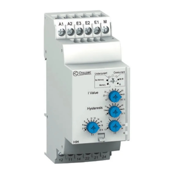
1 - Configuration: selection of the active function (Undercurrent/Overcurrent)
and the operating mode (with or without memory: Memory - No Memory)
2 - Current threshold adjusting potentiometer. I Value
3 - Hysteresis control potentiometer. Hysteresis
4 - Time delay control potentiometer. Tt
5 - Power supply status (green) LED. Un
6 - Relay output status (yellow) LED. R
7 - Startup inhibition delay control potentiometer. Ti
8 - 35 mm rail clip-in spring.
1 - Configuration : choix de la fonction active (Undercurrent/Overcurrent)
et du mode de fonctionnement (avec ou sans mémoire : Memory - No Memory)
2 - Potentiomètre de réglage du seuil de courant. I Value
3 - Potentiomètre de réglage de l'hystérésis. Hysteresis
4 - Potentiomètre de réglage de la temporisation. Tt
5 - LED d'état (verte) de l'alimentation. Un
6 - LED d'état (jaune) de la sortie relais. R
7 - Potentiomètre de réglage de la temporisation d'inhibition au démarrage. Ti
8 - Ressort de clipsage sur rail de 35 mm.
1 - Konfiguration: Wahl der aktiven Funktion (Undercurrent/Overcurrent)
und des Betriebsmodus (mit oder ohne Speicher: Memory - No Memory)
2 - Potentiometer zur Einstellung des Stromschwellenwerts. I Value
3 - Potentiometer zur Einstellung der Hysterese. Hysteresis
4 - Potentiometer zur Einstellung der Verzögerung. Tt
5 - Status-LED (grün) der Stromversorgung. Un
6 - Status-LED (gelb) des Relaisausgangs. R
7 - Potentiometer zur Einstellung der Anlauf-Überbrückungsverzögerung. Ti
8 - Klemmfeder auf 35 mm Schiene.
1
2
Click!
6
mm
0.24
inch
mm 2
0,5...2,5
AWG
20...14
Pozidriv n° 0
Ø 4 mm/
0.16 inch
HIH
1
A1
A2 E3 E2 E1 M
2
Undercurrent
Overcurrent
3
No Memory
No M
Memory
M
I Value
30
80
20
90
4
10
100%
15
40
Hysteresis
10
45
5
50%
8 10 12 14
1
2
6
16
5
4
18
Un
2
1
20s
0,1
3s
Ti
Tt
R
6
7
12
11
14
22 21 24
8
0,5...1,5
20...16
Nm
0,6...1
lb-inch
5.3...8.8
A1
A2 E3 E2 E1 M
I Value
Hysteresis
Un
Ti
Tt
R
12
11
14
22 21 24
35/1.38
1 - Configuración: selección de la función activa (Undercurrent/Overcurrent)
y del modo de funcionamiento (con o sin memoria: Memory - No Memory)
2 - Potenciómetro de ajuste del umbral de corriente. I Value
3 - Potenciómetro de ajuste de la histéresis. Hysteresis
4 - Potenciómetro de ajuste de la temporización. Tt
5 - LED de estado (verde) de la alimentación. Un
6 - LED de estado (amarillo) de la salida relé. R
7 - Potenciómetro de ajuste de la temporización de inhibición
en el arranque. Ti
8 - Molla di aggancio su barra metallica da 35 mm.
1 - Configurazione: scelta della funzione attiva (Undercurrent/Overcurrent)
e della modalità di funzionamento
( con o sin memoria: Memory - No Memory)
2 - Potenziometro di regolazione della soglia di corrente. I Value
3 - Potenziometro di regolazione dell'isteresi. Hysteresis
4 - Potenziometro di regolazione della temporizzazione. Tt
5 - LED di stato (verde) dell'alimentazione. Un
6 - LED di stato (giallo) dell'uscita relè. R
7 - Potenziometro di regolazione della temporizzazione d'inibizione
all'avviamento. Ti
8 - Resorte de clipsado en carril 35 mm.
Rail 35 mm /1.38 inch
Rail 35 mm /1.38 inch
Schiene 35 mm /1.38 inch
Riel 35 mm /1.38 inch
2
Guida 35 mm /1.38 inch
1
Typical
value
c 24 V
2 x 5 A
a 24 V
2 x 5 A
a 250 V max
2 x 5 A
69/2.72
IEC/EN 60715
100 000
2 x 1 A
100 000
100 000
2 x 2 A
100 000
100 000
2 x 2 A
100 000
mm
inch
NTR 1002 C
05 - 2008
1/4