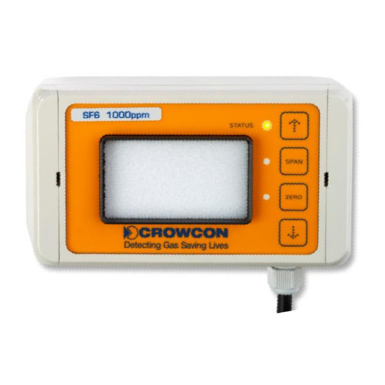
Crowcon 40/40M Руководство по эксплуатации и техническому обслуживанию - Страница 4
Просмотреть онлайн или скачать pdf Руководство по эксплуатации и техническому обслуживанию для Детекторы газа Crowcon 40/40M. Crowcon 40/40M 20 страниц. Infra-red sf6 and refrigerant gas detector

F-Gas Detector Instructions
Never attempt to dismantle this device by yourself in order to tamper with its hardware or to
attempt to dismantle this device by yourself in order to tamper with its hardware or to
attempt to dismantle this device by yourself in order to tamper with its hardware or to
alter its software.
Any mechanical damage, such as opening of glued pipe connections or gaskets or the
Any mechanical damage, such as opening of glued pipe connections or gaskets or the
Any mechanical damage, such as opening of glued pipe connections or gaskets or the
loosening of screws will result in the termination of all
will result in the termination of all liability and warranty granted by
Crowcon Detection Instruments Ltd.
Crowcon Detection Instruments Ltd.
2. Installation
2.1.
Operating voltage
The F-Gas detector is designed to operate in a range of an input voltage of 12 to 2
faultless operation is guaranteed
faultless operation is guaranteed within these parameters. Supply voltage fluctuations
be kept as small as possible.
kept as small as possible.
All connections used for supply and output signals are available from connector
All connections used for supply and output signals are
and can be accessed by opening the transmitter casing – see fig. 2.
and can be accessed by opening the transmitter casing
Figure 2: Opened transmitter casing with interface electronics
Figure 3: connector ST1 – connection for power supply, analogue output and the RS485 interface
voltage and analogue outputs (general)
designed to operate in a range of an input voltage of 12 to 2
designed to operate in a range of an input voltage of 12 to 28Vdc. A
2: Opened transmitter casing with interface electronics
Connection of the supply voltage 12 to 28Vdc.
V+
V+
Analogue output signal (optionally 0-20mA; 4- 20mA or 0 to
I
0V (common ground for V+, I and RS485 (not yet implemented)
GND
GND
Non inverted signal line for the integrated RS485 interface (not yet implemented)
Non inverted signal line for the integrated RS485 interface (not yet implemented)
RS+
RS+
Inverted signal line for the integrated RS485 interface (not yet implemented)
Inverted signal line for the integrated RS485 interface (not yet implemented)
RS
RS-
connection for power supply, analogue output and the RS485 interface
connection for power supply, analogue output and the RS485 interface
liability and warranty granted by
voltage fluctuations must
connector ST1 (fig. 2)
Connector ST1
V+
I GND RS+ RS-
20mA or 0 to 2/5/10V).
(not yet implemented)).
