Crowcon Flamgard-Plus Инструкции - Страница 2
Просмотреть онлайн или скачать pdf Инструкции для Детекторы газа Crowcon Flamgard-Plus. Crowcon Flamgard-Plus 5 страниц. Flameproof flammable gas detector with non-intrusive one-man calibration
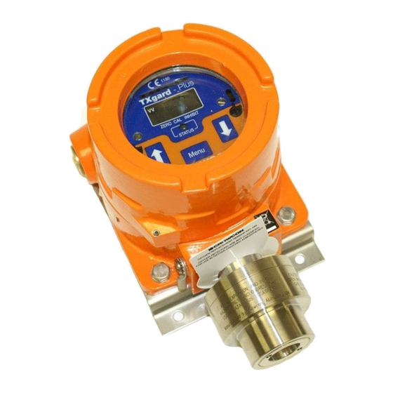
1.3 Status Indication
Flamgard Plus includes a local display and status LED, visible through the
junction box window. This is shown in Diagram 1.
The display shows the current flammable gas concentration in the
range 0-100%LEL and current mode of operation ie NORMAL, ZERO or CAL.
The LED shows the current alarm state of the detector. This is summarised in
Table 1.
Operational
LED
4-20mA
state
indication
outputs*
Normal
Steady green
4 to 7.2mA
operation
Normal
Steady red
7.2 to 10.4mA
operation
(Alarm 1)
Normal
Flashing red
10.4 to 20mA
operation
(Alarm 2)
Over-range
Flashing red
24mA (clamp)
Zero/calibration Flashing green
Configuration
mode
dependent
(see section 2)
Detector
Steady amber
0mA
fault
*As standard, AL1 = 20%LEL and AL2 = 40%LEL
Relay version only
Table 1: LED status indicator summary.
2. DETECTOR CONFIGURATION
2.1 Standard configuration
As standard, Flamgard-Plus is factory set as follows:
Current source with 0 mA
2 mA
4-20 mA = Normal operation
24 mA
AL1 relay
Alarm level 1 set to 20%LEL
Normally de-energised, energising on alarm
Contact normally open (NO), closing on alarm
AL2 relay
Alarm level 2 set to 40%LEL
Normally de-energised, energising on alarm
Contact normally open (NO), opening on alarm
FAULT relay
Normally energised, de-energising on fault
Contact normally closed (NC), opening on fault
Alarm/fault relays automatically reset when alarm or fault has cleared.
INHIBIT
Normally selected. ie. when CAL/ZERO selected
current output is forced to 2mA and relays are held in
normal/no alarm state.
Location of links are shown in Diagram 2.
2.2 4-20mA options
To change current source output to sink, set switch to 'SK' position.
To change Inhibit from 2 mA to 4 mA, fit link to '4' position.
2.3 Relay options
To change AL1 or AL2 relay from NO to NC, fit link in the 'NC' position.
To change FAULT relay from NC to NO, fit link in the 'NO' position.
2.4 Inhibit options
To not inhibit 4-20 mA signal and relays, fit link to 'N' and link to '4'.
Relay
Comment*
states*
AL1 - Off
0 to 20% LEL
AL2 - Off
FAULT - On
AL1 - On
20 to 40% LEL
AL2 - Off
FAULT - On
AL1 - On
40 to 100% LEL
AL2 - On
FAULT - On
AL1 - On
>100% LEL
AL2 - On
Display back-
FAULT - On
light flashes
Configuration
Latched until
dependent
reset via 'MENU'
(see section 2)
AL1 - Off
AL2 - Off
FAULT - Off
= Fault
= Inhibit ie. Zero/Cal mode
= Over-range clamp
3. INSTALLATION
WARNING
Flamgard Plus is designed for use in Zone 1 and 2 hazardous areas and
is certified EEx d IIC T6 (AEx d IIC T6 in USA). Installation must be in
accordance with the recognised standards of the appropriate authority
in the country concerned. For more information contact Crowcon.
Prior to carrying out any work ensure local regulations and site
procedures are followed.
3.1 Location
There are no rules which dictate the siting and location of detectors, however,
considerable guidance is available from BS6959:1988 – 'British Standard
Code of Practice for the Selection, Installation, Use and Maintenance of
Apparatus for the Detection and Measurement of Combustible Gases'. In the
USA refer to the National Electrical Code (NEC 1999). Similar international
codes of practice may be used where applicable. In addition certain regulatory
bodies publish specifications giving minimum gas detection requirements for
specific applications.
The detector should be mounted where the gas is most likely to be
present. The following points should be noted when locating flammable gas
detectors:
• To detect gases which are lighter than air e.g. methane, detectors should
be mounted at high level and Crowcon recommend the use of a Collector
Cone, Part No. C01051.
• To detect heavier than air gases e.g. butane, detectors should be mounted
at low level.
• When locating detectors consider the possible damage caused by natural
events e.g. rain or flooding. For detectors mounted outdoors Crowcon
recommend the use of a Weatherproof Cap, Part No. C01442.
• Consider ease of access for functional testing and servicing.
• Consider how the escaping gas may behave due to natural or forced air
currents. Mount detectors in ventilation ducts if appropriate.
• Consider the process conditions. Butane is normally heavier than air, but if
released from a process line which is at an elevated temperature and/or
under pressure the gas may rise rather than fall.
The placement of detectors should be determined following advice of
experts having specialist knowledge of gas dispersion, the plant processing
equipment as well as safety and engineering issues. The agreement reached
on the locations of sensors should be recorded. Crowcon would be
pleased to assist in the selection and siting of gas detectors.
3.2 Mounting
The mounting detail of Flamgard Plus is given in Diagram 1. Flamgard Plus
should be installed at the designated location with the detector pointing down.
This ensures that dust or water will not collect on the sinter and stop gas
entering the detector.
3.3 Cabling Requirement
Cabling to Flamgard Plus must be in accordance with the recognised
standards of the appropriate authority in the country concerned and meet the
electrical requirements of the detector. Crowcon recommend the use of steel
wire armoured (SWA) cable and suitable explosion proof glands must be
used. Alternative cabling techniques, such as steel conduit, may be
acceptable provided appropriate standards are met.
Flamgard Plus requires a dc supply of 10-30 V at up to 210 mA.
Ensure the minimum dc supply of 10 V is observed at the detector, taking into
account the voltage drop due to cable resistance.
For example, a nominal dc supply at the control panel of 24 V has a
guaranteed minimum supply of 18V. The maximum voltage drop
allowed is therefore 8V. Flamgard Plus can demand up to 210 mA and so the
maximum loop resistance allowed is 38 Ohms. A 1.5 mm
allow cable runs up to 1500 m. Table 2 shows maximum cable distances
given typical cable parameters.
2
2
cable will typically