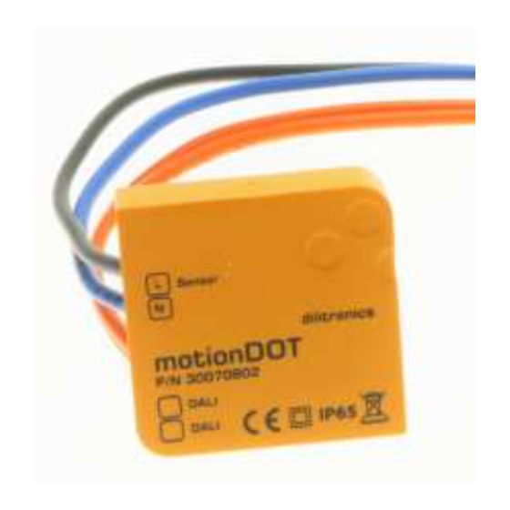
Dilitronics motionDOT Инструкция по эксплуатации
Просмотреть онлайн или скачать pdf Инструкция по эксплуатации для Датчики безопасности Dilitronics motionDOT. Dilitronics motionDOT 2 страницы.

motionDOT
• DALI motion sensor interface
• Controlling of DALI groups or DALI broadcast commands
• To upgrade any conventional motion sensor
• Multi-controller capability
Operating Instruction
01.
Safety and installation notes
The DALI bus possibly is not subject of the requirements of Safety Extra Low Vol-
tage (SELV). So the mounting and installation of the motionDOT must be carried
out only by qualified electricians.
Never work on the system with applied voltage. Hazard-mortal danger!
Please read instructions before starting implementation
Ensure that the power supply of the DALI bus is turned off.
02.
General information
The motionDOT module allows to convert switching signals of the motion sensor
into DALI switching commands to DALI group addresses or as a broadcast*. To
use this module, commercially available motion sensor can be connected.
*A DALI broadcast command addresses all devices that are connected to a
DALI network.
The CE Declaration of Conformity can be downloaded from the website
www.dilitronics.com.
Brightness
(Luminai re / group of luminair es )
Maximum
level
Stand-by
level
03.
Mounting
Place the motionDOT in the installation socket. Make sure that no wires are bent
and the screws do not damage any wires.
04.
Connection
Connect the blue cable of the motionDOT to the switch output marked
by „N" of the motion sensor. Connect the black cable of the moti-
onDOT
to
the
switch
output
Connect the two orange connection cables of the motionDOT module to the DALI
bus. The polarity of the DALI bus is not important for this.
L
N
PE
DA
DA
N
PE
L
N
L'
Adjustable
on the motion sensor
5
5
0
0
Min. brightness
adjustable on
the motionDOT
Time
marked
by
„L"
of
the
motion
DALI
DALI
N Sensor
L Sensor
5
5
0
0
DALI group selection
or broadcast selection
Brightness
Stand-by Level
www.dilitronics.com ● [email protected] ● Service hotline +49 3641 8757577
dilitronics GmbH ● Felsbachstraße 5 ● 07745 Jena / Germany
05.
Selection of the command receiver
If the switch position "0" of the rotary switches is at the bottom, as shown in Fig.
2, the left rotary switch is used for setting the DALI address.
Left Switch position:
0-7: Via these numbers, one of the 8 addressable groups can be accessed by
the motion sensor.
8: Via this number the motionDOT is defined for sending commands as broad-
cast.
Switch position of the left rotary switch
0
1
...
7
8
9
**The DALI standard demands the implementation of collision check modes for
multi-master control units. In normal operation, the „9" position of the switch
must be absolutely avoided, because otherwise the DALI bus is completely occu-
pied by test messages and another communication is not possible!
06.
Selection of the brightness in stand-by level
If the switch position "0" of the rotary switches is at the bottom, as shown in
Fig. 2, the right rotary switch is used for setting the brightness level to which
the luminaire or a group of luminaires will be dimmed after the motion sensor is
switched off again (stand-by level).
Fig. 1
Switch position of the right rotary
switch
0
1
2
3
4
5
sensor.
6
7
8
9
07.
Confi guration of the motion sensor
Now you can configure the conventional motion sensor.
08.
Disposal of electrical waste
Your product is designed and manufactured with high quality materials and com-
ponents, which can be recycled and reused. When you see the crossed-out
wheeled bin symbol attached to a product, it means the product is covered by
the European Directive 2002/96/EC:
Never dispose of your product with other household waste. Please inform your-
self about the local rules on the separate collection of electrical and electronic
products. The correct disposal of your old product helps prevent potentially
Fig. 2
negative consequences for the environment and human health.
Motion sensor sends commands to
G0 (group)
G1 (group)
...
G7 (group)
Broadcast
collision check mode**
DALI-brightness of the luminaire(s)
Stand-by level
0 (luminaire(s) is (are) switched off
25
50
75
100
125
150
175
200
225
motionDOT
EN I Operating Intruction
20120905
Technical changes and mistakes reserved.
