Crowcon 96HD/OX Краткое руководство по эксплуатации - Страница 3
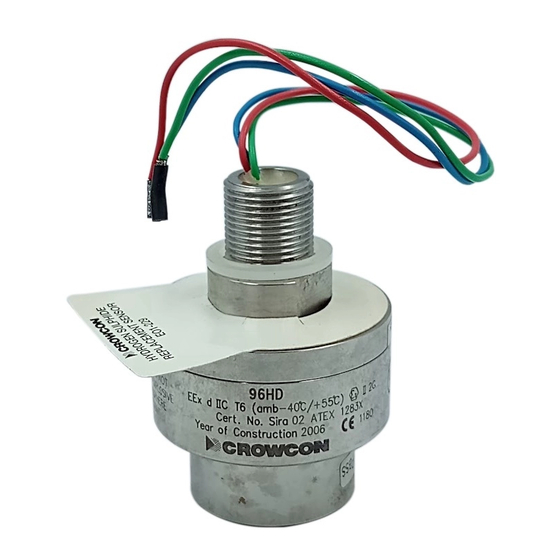
Просмотреть онлайн или скачать pdf Краткое руководство по эксплуатации для Аксессуары Crowcon 96HD/OX. Crowcon 96HD/OX 3 страницы. Sensor housing
4. OPERATION
4.1 Setting up
Please refer to the original instruction manual as this procedure may vary
depending on the type of equipment the 96HD is connected to.
4.1.1 Flammable sensors only
If 96HD is used to replace flammable detectors connected to
conventional control equipment (ie 3 wire mV bridge configuration) the
correct bridge voltage must be applied to the detector. This varies
depending on the sensor fitted and is summarised in Table 3. Sensor
part number labels are located on the outside of the 96HD housing.
Sensor
Element Bridge Volts
Comment
Part No.
(V dc)
S01-637/A
VQ21T
2.0
Poison resistance alternative
B
300P
2.0
Poison resistance
C
VQ8
2.5
Lead resistance
D
VQ16
2.5
Early model
E
VQ22
2.0
Low power for
marine applications
F
VQ25
2.0
For halogens
G
VQ41
2.0
For ammonia/aviation fuel
H
VQ1
2.0
Early model
Table 3: Bridge voltage requirements for flammable sensors.
The voltage must be measured in the junction box between the red (-ve)
and black (+ve) wires and should be +/- 0.1 V dc of the stated value. For
setting up instructions refer to the original equipment instruction manual.
Site practices will dictate the frequency with which detectors are tested.
Crowcon would recommend that detectors be gas tested at least every
6 months and re-calibrated as necessary. To re-calibrate a detector refer
to the original equipment instruction manual.
7
NOTES
Area Classifications:-
Zone 0:
An area classified, as Zone 0 will have ignitable
concentrations of flammable gases, vapours or
liquids present continuously or for long periods of
time under normal operating conditions.
Zone 1:
An area classified, as Zone 1 is likely to have
ignitable concentrations of flammable gases,
vapours or liquids present under normal operating
conditions.
Zone 2:
An area classified, as Zone 2 is not likely to have
ignitable concentrations of flammable gases,
vapours or liquids present under normal operating
conditions.
11
4.3 Sensor replacement/servicing of detectors
WARNING
This work should be carried out by Crowcon or an approved
service centre unless suitable training has been received.
The 96HD sensor housing allows the user to replace the
sensors, gaskets and sinter if necessary. An exploded view of the 96HD
sensor housing is given in Diagram 2 for reference. The following
procedure may be followed when servicing a 96HD device.
a Open the 96HD sensor housing by removing the four Allen head
screws from the Top Cap with a 3mm Allen key.
b Remove the sensor from the Top Cap PCB. Flammable sensors
have an extra black sleeve which may be separate from the sensor.
This is normal and the sleeve may be re-used.
c Fit the replacement sensor checking the part number is correct. This
part number is labelled on the main body of the detector.
Observe pin alignment with PCB.
d Inspect the gaskets and replace if necessary.
e The sinter assembly will only need to be replaced if it has become
blocked by dust or oil. Such blockage causes the response time of
the detector to be slow and may affect sensitivity. To remove the
sinter a removal tool (Part # M01614) is required. Loctite No 243
must be used on the sinter assembly threads to maintain
certification.
f
Re-assemble the 96HD housing taking time to ensure that the 3 mm
Allen head screws are securely fixed into position.
g The 96HD is ready for use with the appropriate detector/system.
8
5. SPARE PARTS AND ACCESSORIES
Description
Part number
Sensors:
Flammable (0-100% LEL)
S01637/letter
See sensor
replacement
label on detector
Thermal conductivity (0-100% vv binary gas)
S01638 / TC
Oxygen (0-25% vv)
E01488 / OX
Toxic (0-25 ppm hydrogen sulphide)
E01229 / HS
Toxic (0-250 ppm carbon monoxide)
E01344 / CO
Toxic (0-50 ppm ammonia)
E01735 / AM
Accessories:
Collector cone
C01051
Weatherproof cap
C01442
Swivel mounting bracket
C01340
96HD to DI5/6, DI8 adaptor
C01664
Service items:
Sinter removal tool
M01614
Loctite No. 243
Contact Crowcon
Sinter assembly
S01781
Gasket 1
M04452
Gasket 2
M04128
Calibration gas
Contact Crowcon
9
6. SPECIFICATION
Material
316 Stainless steel
Dimensions
Max diameter 55mm (2.2 inches)
Overall length 72mm (2.8 inches)
(60mm (2.4 inches) fitted to junction box)
Weight
0.5 kg (1.1 lbs)
Electrical Output
Sensor dependent
Operating temperature
Flammable -40 to +55
o
C (-40 to 131
Toxic -10 to +55
o
C (14 to 131
o
F)
Humidity
0-99% RH non-condensing
Degree of protection
IP66 when fitted with weatherproof cap
and connected to suitable junction box
Approval code
II 2 G EEx d IIC T6 (+55
o
C)
Safety Certificate No.
Sira02ATEX1283X
Standards
EN50014, EN50018, EN50270
Zones
Certified for use in Zone 1 or Zone 2
areas. (see area classifications section)
Gas groups
IIA, IIB, IIC
Termination
Must be used with suitable certified
junction box or transmitter/amplifier
Note: The 96HD detector must be effectively earthed for electrical
safety and to limit the effects of radio frequency interferance. This may
be achieved by mounting the 96HD into an earthed Exd junction box or
an Exe plastic junction box fitted with an earth continuity plate. There
are no internal connections to the 96HD head body.
10
o
F)