Acuity Controls nLIGHT Карманное руководство - Страница 2
Просмотреть онлайн или скачать pdf Карманное руководство для Фонарь Acuity Controls nLIGHT. Acuity Controls nLIGHT 5 страниц. Enabled digital
luminaire
Также для Acuity Controls nLIGHT: Инструкции по программированию (2 страниц)

Terminology
Understanding these terms will help you make the most of this guide.
nLight device - An intelligent digital device having the ability to
communicate over an nLight network. Device types include occupancy
sensors, photocells, power/relay packs, wall switches, dimmers and panels.
Blink Codes – nLight devices show status and diagnostic codes by blinking
their LED(s) in defined patterns.
CAT-5e – network cable to connect nLight devices. The T568B wiring
standard is recommended for the order of conductors in the cable terminator
(plug).
RJ 45 – Physical standard describing the mating connectors used on CAT-5e
cabling in both nLight 485 Bus networks and IEEE 802.3 Ethernet networks.
485 Bus – the CAT-5e cable connecting the devices in an nLight Control
Zone. The bus enables communications between devices using the TIA-485
Standard and carries low-voltage DC operating power for the devices.
Lighting Zone – A group of lights wired or configured to operate together.
Control Zone – A collection of nLight devices and/or nLight-enabled
luminaires that function together in order to control a space's lighting.
Typically, one control zone per room is used, however large areas (such as
warehouses) may require multiple zones. Zones can also be subdivided via
configuration to cover several small rooms.
Out of the Box - It Just Works
nLight devices ship with default settings so that they simply work, right
out of the box. With as little as a switch or sensor and a Power Pack wired to
lights, you can create a perfectly functional nLight Control Zone.
Consider a simple office with an nPODM wall switch and a Power Pack
wired to the room's light fixture. The nPODM broadcasts switch status
(ON/OFF) on Channel 1, and the Power Pack tracks (obeys) switch status
changes on Channel 1. Right out of the box, the nPODM can control the
room's lighting.
This table shows default Broadcast (status) channels for a sampling of
nLight WallPod switches, and default Tracking (listening) channels for
common Power Pack devices; devices with 2P or 4P indicate multiple poles.
Device
1
nPODM
X
nPODM 2P
X
nPODM 4P
X
nPP16
X
nSP16
X
nSP5 2P
X
Occupancy Channel (default) - All sensors broadcast on Channel 1.
All devices tracking, track Occupancy Channel 1.
Photocell Channel (default) - All sensors broadcast on Channel 1.
All devices tracking, track Photocell Channel 1.
Defaults
Broadcast
Occupancy
Channel 1
Photocell
Channel 1
Switch Channel
2
3
4
X
X
X
X
X
Track
Channel 1
Channel 1
Backbone – The communication network formed by nLight Bridges and
Gateway devices that is required to deploy remote or time-based changes,
such as a scheduled override, out to a device, groups of devices, or zone(s).
Additionally, advanced features, such as performance monitoring and
interfacing with higher level BMS systems, require the end-to-end network
connectivity that the backbone provides.
Bridge (nBRG 8) – nLight backbone device with 8 RJ-45 ports to
connect control zones, other Bridges, or a Gateway. Bridges act as hubs
by aggregating communication traffic from connected zones onto the
backbone. Bridges also act as routers by forwarding information from the
backbone out to the applicable zones. Additionally, Bridges combine system
power from zones that are net contributors of power and distribute it to
zones that are net consumers of power.
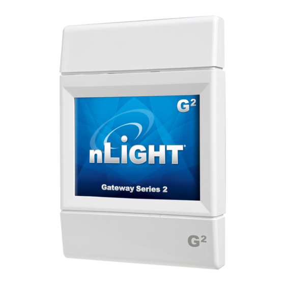
Gateway – An nLight backbone device that maintains a database of all
downstream nLight devices, provides time clock functionality, stores custom
operating profiles, and displays system status. Gateways also link an nLight
backbone to the host computer of the SensorView Management software
via an Ethernet LAN/WAN network. The Gateway consists of a touch screen
display (nGWY2 GFX), controller (nGWY2 CTRL), and power supply (PS 250).
WallPod® (or nPODM) – general term for an nLight wall station. WallPods
are available in many configurations that enable occupants to issue On,
Off, Raise, Lower, and/or Scene selection commands. WallPods have model
numbers that start with nPOD(M).
nLight Power Considerations
Each nLight zone supports up to 128 devices. Some devices provide power,
others consume it. Most nLight devices use only 3-4 mA, some up to ~8mA;
nLight power generating devices typically provide 30-40 mA per RJ-45 port.
For nLight zones with more than 6 or 8 devices, you should carefully budget
power consumption to ensure that all devices have adequate power. Device
data sheets give accurate power generation or consumption values.
Tips to avoid Low Voltage in a Zone
• Remember that nLight device placement is flexible. Locate Power
Packs mid-Zone. Ex: in an 11-device Zone, place Power Pack as device
#6. Each side of the Power Pack offers 40mA, or 8mA per device. If the
Power Pack were device #1 or #11, less power is available per device.
• Calculate the power load and make sure there are enough power-
supplying devices placed appropriately in the Zone.
• A Bridge can redistribute power from Zones with a surplus to Zones
with a deficit. When coupled with a PS150 supply, a Bridge has
~90mA available to share with connected Zones that need power.
• If a Bridge is accessible, consider splitting heavily-loaded Zones into
multiple Zones with lower device counts.
The illustration below shows how a Bridge can share power with Zones that
need it, as well as re-distribute power from Zones with excess voltage.
nPP16
40mA
1
nPS80
40mA
2
nPP16
40mA
3
40mA
~90mA
for Bridge
40mA
208mA
available to share
among ports
40mA
38mA
40mA max
4
40mA max
5
40mA max
6
40mA max
7
40mA max
8
