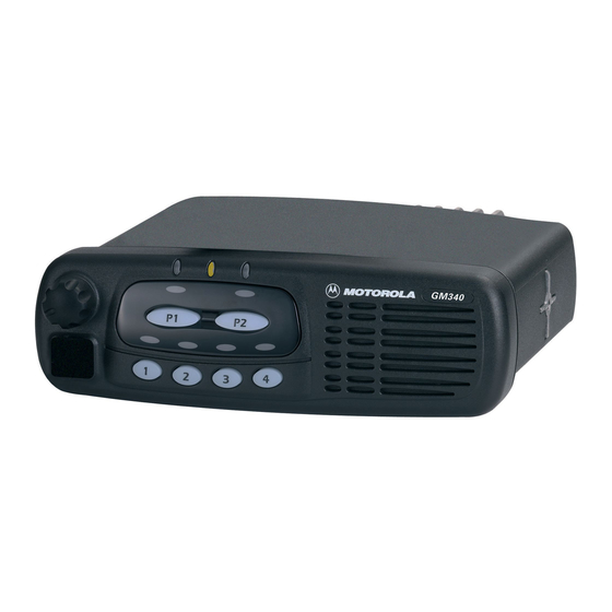
Motorola GM Series Руководство по установке - Страница 22
Просмотреть онлайн или скачать pdf Руководство по установке для Радио Motorola GM Series. Motorola GM Series 36 страниц. Professional radio
Также для Motorola GM Series: Информация о сервисе (34 страниц), Руководство по эксплуатации (28 страниц)

1-14
Pin
Function
11
Receiver Audio
(NPD Data In)
12
Digital In/Out 7
(CTS)
13
Switched
Battery Voltage
14
Digital In/Out 8
Hook (Clear)
15
RSSI
16
External
Speaker +
17
Bus +
18
Boot Control
19
Reserved
20
Reserved
Note 1:
Note 2:
Note 3:
Note 4:
Table 1-4 Connector Pin Functions
There are two possible outputs: (1) Discriminator Audio; and (2) Continuous
filtered RX audio. The nominal output level for Discriminator Audio is
330m Vrms at 60% deviation and for Filtered Audio 600m Vrms at 60%
deviation at 1kHz. Function depends on dealer programming. For NPD calls,
this uses discriminator audio and cannot be configured by the CPS.
This digital input/output function depends on dealer programming.
This voltage is available when the radio is switched on. The maximum current
is 1A.
This is a digital input/output depending on dealer programming.
(See Notes 1, 2).
This hook line is in parallel to the hook line of the control head microphone
connector. This port reads "0" when the microphone is on-hook and "1" when
off-hook. It is assumed that the hook is a mechanical switch, so the software
will always debounce this input.
This is an analog output which indicates the strength of the received signal.
Positive output of radio's audio PA (see Pin 1).
This pin is used for flashing and for programming the radio.
To enter Boot Mode this line must be connected to ground when the radio is
switched on.
Reserved.
Reserved.
Digital Input
4.7 k Ω Internal Pull Up Resistor to +5V.
Maximum Input Voltage accepted as Low = 0.6V
Minimum Input Voltage accepted as High = 3.0V
Digital Output
4.7k Ω Internal Pull Up Resistor to +5V
Maximum Current when Output Low = 10mA
Maximum Voltage when Output Low = 0.5V @ 10mA
High Current Digital Output
4.7k Ω Internal Pull Up Resistor to continuous B+
Maximum Current when Output Low = 200mA
Maximum Voltage when Output Low = 1.7V @200mA
Digital Input
10k Ω Internal Pull Up Resistor to +5V
Maximum Input Voltage accepted as Low = 0.6V
Minimum Input Voltage accepted as High = 3V
Description
INSTALLATION
