Motorola GM360 Информация о сервисе - Страница 13
Просмотреть онлайн или скачать pdf Информация о сервисе для Радио Motorola GM360. Motorola GM360 32 страницы. Gm series professional radio uhf (403-470mhz)
Также для Motorola GM360: Информация о сервисе (34 страниц), Информация о сервисе (32 страниц)

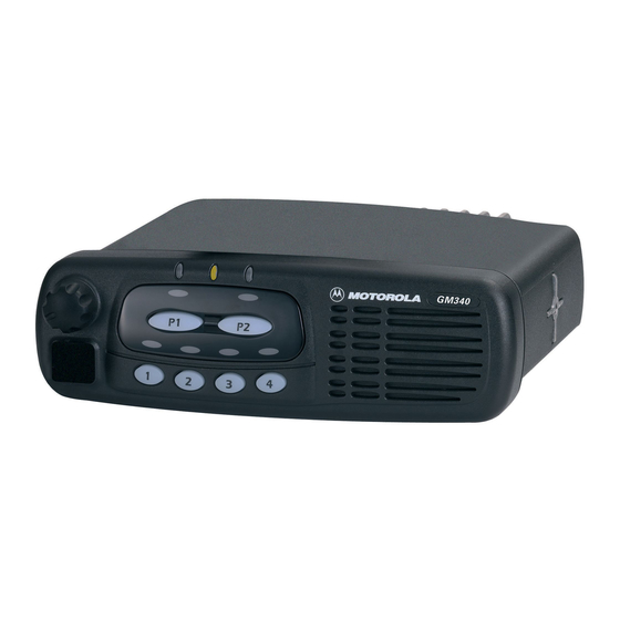
Controlhead Model for GM160, GM360 and GM660
includes the RAM start address for the following display data. With input A0 set to logic „1" the µP
then writes the display data to the display RAM. When data transfer is complete the µP terminates
the chip select, RD and WD activities.
The display driver's power circuit provides the voltage supply for the display. This circuit consists of a
voltage multiplier, voltage regulator and a voltage follower. The external capacitors C0971 - C0973
configure the multiplier to double the supply voltage. In this configuration the multiplier output VOUT
(U0971-8) supplies a voltage of -5V (2* -5V below VDD). The multiplied voltage VOUT is sent to the
internal voltage regulator. To set the voltage level of the regulator output V5 (U0971-5) this voltage is
divided by the resistors R0973 and R0974 and fed back to the reference input VR (U0971-6). In
addition the regulator output voltage V5 can be controlled electronically by a control command sent
to the driver. With the used configuration the voltage V5 is about –2V. The voltage V5 is resistively
divided by the driver's voltage follower to provide the voltages V1 - V4. These voltages are needed for
driving the liquid crystals. The level of V5 can be measured by one of the µP's analogue to digital
converters (U0831-20) via resistive divider R0975, R0976. To stabilize the display brightness over a
large temperature range the µP measures the temperature via analogue to digital converter (U0831-
18) using temperature sensor U0834. Dependent on the measured temperature the µP adjusts the
driver output voltage V5, and in turn the display brightness, via parallel interface.
3.8
Microphone Connector Signals
Signals BUS+, PTT IRDEC, HOOK, MIC, HANDSET AUDIO, FLT A+, +5V and 2 A/D converter
inputs are available at the microphone connector J0811. Signal BUS+ (J0811-7) connects to the
SBEP bus for communication with the CPS or the Universal Tuner. Line MIC (J0811-5) feeds the
audio from the microphone to the radio's controller via connector J0801-4. Line HANDSET AUDIO
(J0811-8) feeds the receiver audio from the controller (J0801-6) to a connected handset. FLT A+,
which is at supply voltage level, and +5V are used to supply any connected accessory like a
microphone or a handset.
The 2 A/D converter inputs (J0811-9/10) are used for a microphone with keypad. A pressed key will
change the dc voltage on both lines. The voltages depend on which key is pressed. The µP
determines from the voltage on these lines which key is pressed and sends the information to the
host radio.
Line PTT IRDEC (J0811-6) is used to key up the radio's transmitter. While the PTT button on a
connected microphone is released, line PTT IRDEC is pulled to +5 volts level by R0843. Transistor
Q0843 is switched on and causes a low at µP port PA2. When the PTT button is pressed, signal PTT
IRDEC is pulled to ground level. This switches off Q0843 and the resulting high level at µP port PA2
informs the µP about the pressed PTT button. The µP will inform the host radio about any status
change on the PTT IRDEC line via SBEP bus.
When line PTT IRDEC is connected to FLT A+ level, transistor Q0821 is switched on through diode
VR0821 and thereby pulls the level on line ON OFF CONTROL to FLT A+ level. This switches on the
radio and puts the radio's µP in bootstrap mode. Bootstrap mode is used to load the firmware into the
radio's flash memory (See controller sub section for more details).
The HOOK input (J0811-3) is used to inform the µP when the microphone´s hang-up switch is
engaged. Dependent on the CPS programming the µP may take actions like turning the audio PA on
or off. While the hang up switch is open, line HOOK is pulled to +5 volts level by R0841. Transistor
Q0841 is switched on and causes a low at µP port PA1. When the HOOK switch is closed, signal
HOOK is pulled to ground level. This switches off R0841 and the resulting high level at µP port PA1
informs the µP about the closed hang up switch. The µP will inform the host radio about any status
change on the HOOK line via SBEP bus.
2-7
