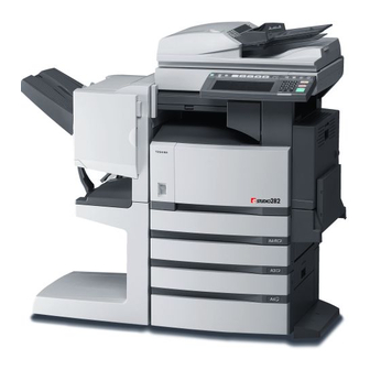
Toshiba E-STUDIO 232 Руководство по эксплуатации - Страница 4
Просмотреть онлайн или скачать pdf Руководство по эксплуатации для Принтер "все в одном Toshiba E-STUDIO 232. Toshiba E-STUDIO 232 20 страниц. Toshiba printer sales guide
Также для Toshiba E-STUDIO 232: Руководство по продажам (48 страниц)

11. DRUM RELATED SECTION ....................................................................................... 11-1
11.1 Configuration ..................................................................................................................... 11-1
11.2 Functions ........................................................................................................................... 11-2
11.3 High-Voltage Transformer Output Control Circuit.............................................................. 11-4
11.3.1 General description ................................................................................................ 11-4
11.3.2 Description of Operation......................................................................................... 11-5
11.4 Drum Temperature Detection Circuit ................................................................................. 11-6
11.4.1 General description ................................................................................................ 11-6
11.4.2 Construction ........................................................................................................... 11-6
11.5 Temperature/Humidity Detection Circuit............................................................................ 11-7
11.5.1 General description ................................................................................................ 11-7
11.5.2 Construction .......................................................................................................... 11-7
11.6 Disassembly and Replacement ......................................................................................... 11-8
12. DEVELOPMENT SYSTEM.......................................................................................... 12-1
12.1 Configuration ..................................................................................................................... 12-1
12.2 Functions ........................................................................................................................... 12-2
12.2.1 General description ................................................................................................ 12-2
12.2.2 Recovered toner supply mechanism ...................................................................... 12-3
12.3 Drive Circuit of Toner Motor............................................................................................... 12-4
12.4 Auto-Toner Circuit.............................................................................................................. 12-6
12.4.1 General description ................................................................................................ 12-6
12.4.2 Function of auto-toner sensor ................................................................................ 12-7
12.5 Disassembly and Replacement ......................................................................................... 12-9
13.1 General Description ........................................................................................................... 13-1
13.2 Operation ........................................................................................................................... 13-2
13.3 Functions ........................................................................................................................... 13-3
13.4 Heater Control Circuit ........................................................................................................ 13-5
13.4.1 Configuration .......................................................................................................... 13-5
13.4.2 Temperature detection section ............................................................................... 13-6
13.5 Disassembly and Replacement ....................................................................................... 13-11
14. PAPER EXIT SECTION .............................................................................................. 14-1
14.1 General Description ........................................................................................................... 14-1
14.2 Functions ........................................................................................................................... 14-2
14.3 Control Circuit of Exit Motor............................................................................................... 14-3
14.4 Exit Motor Drive ................................................................................................................. 14-4
14.5 Disassembly and Replacement ......................................................................................... 14-5
15. AUTOMATIC DUPLEXING UNIT (ADU) (OPTION: MD-0102) .................................. 15-1
15.1 General Description ........................................................................................................... 15-1
15.2 Description of Operations .................................................................................................. 15-2
15.3 Drive of ADU...................................................................................................................... 15-7
15.4 Flow Chart ......................................................................................................................... 15-8
15.5 Disassembly and Replacement ....................................................................................... 15-10
16. POWER SUPPLY UNIT .............................................................................................. 16-1
16.1 Construction....................................................................................................................... 16-1
16.2 Operation of DC Output Circuits ........................................................................................ 16-2
16.3 Output Channel ................................................................................................................. 16-3
16.4 Fuse................................................................................................................................... 16-5
16.5 Configuration of Power Supply Unit................................................................................... 16-6
16.6 Sequence of Power Supply ............................................................................................... 16-7
16.7 AC Wire Harness ............................................................................................................... 16-8
17. PC BOARDS ............................................................................................................... 17-1
June 2004 © TOSHIBA TEC
e-STUDIO200L/202L/230/232/280/282 CONTENTS
3
