ABB CM-UFD.M22 Инструкции по эксплуатации и установке - Страница 6
Просмотреть онлайн или скачать pdf Инструкции по эксплуатации и установке для Реле ABB CM-UFD.M22. ABB CM-UFD.M22 13 страниц. Grid feeding monitoring relay, cm range

Local command and external signal
The CEI 0-21 standard defines "restrictive thresholds", the under-
and overfrequency thresholds S1 (49.5-50.5 Hz), and "permissive
thresholds", the under- and overfrequency thresholds S2 (47.5-
51.5 Hz). Selection of S1 or S2 thresholds is made by the
corresponding combination of the external signal and the local
command, as shown (see tables below).
Remote trip
The control input Y3-Y0 can be configured as normally open or
normally closed. If normally closed is configured, the grid feeding
monitoring relay trips if Y3-Y0 is opened. If normally open is
configured, the relay trips if Y3-Y0 is closed.
Within less than 20 ms after activation of the remote trip input,
output relay R1 de-energizes, and output relay R3 energizes or de-
energizes, depending on the configuration. When the remote trip
input is deactivated the output relays R1 and R3 energize or de-
energize depending on the configuration (closed- or open-circuit
principle).
Operation principle
Input state
normally open
open
normally open
closed
normally closed
open
normally closed
closed
Truth table for control inputs External Signal Y2-Y0 and Remote
trip Y3-Y0
External signal
Local command
0
disabled
1
disabled
0
enabled
1
enabled
Truth table for frequency thresholds
Auto test
The auto test function allows the verification of the protective
functions by increasing the lowest threshold and decreasing the
highest threshold respectively, until the measured value for input
voltage or frequency equals the threshold. Confirming the start of
the auto test routine initiates the threshold sweep with the
objective of tripping the relay. For each threshold the device will
display the measured switching time by monitoring the feedback
signal from the external contact of the switching device.
If the auto test fails, the cause of error has to be analysed and the
test needs to be repeated. Output relay R1 remains de-energized
as long as the test has not been passed successfully.
Note: We recommend to manually disconnect the generating plant
from the grid before executing the auto test procedure. The auto
test will cause the CM-UFD.M22 to trip four times within a short
time, which may lead to voltage fluctuations in the public grid.
Error memory
The relay records and logs the last 99 events that caused tripping
of the relay and any interruption of the control supply voltage. The
type of error as well as the current value of the operation counter
are recorded into the internal error list, accessible in the menu
"Error memory". The list is stored internally in a non-volatile
memory which can be reset by the user.
Note: Remote trip and Power OFF events can fill the error memory
of max. 99 events very fast. Thus other trip events might not be
visible if the CM-UFD.M22 is often switched on and off or many
remote trip signals are common in your application. This is why
recording of these two events can be disabled.
Control input
0
1
1
0
Active thresholds
only S2
only S2
only S2
S1 and S2
ROCOF (Rate of change of frequency)
This function is monitoring the rate of change of frequency within a
very short time and is intended to detect a trend towards a
imminent loss of mains (islanding), which might occur if a failure in
the mains happens. The ROCOF monitoring function is
deactivated per default.
The error time is the duration for which output relay R1 shall
remain open and the error message is displayed.
Neutral conductor monitoring
Neutral conductor monitoring is always active when phase-neutral
measuring principle is selected in menu "Nominal voltage". The
interruption of the neutral conductor will result in an immediate
tripping of relay R1 (DDI).
Password
Any CM-UFD.M22 relay is delivered with the same default
password [0000) for protection of its settings and local commands:
the installer is responsible for the verification of the parameter
values and the change of the password with a personal one in
order to avoid unwanted modifications.
Configuration
Back light of the display switches off automatically after an
adjustable duration. With a dark display, press any button to light
it up again.
The display switches off automatically after 1 hour. With a switched
off display, press any button to switch it on again.
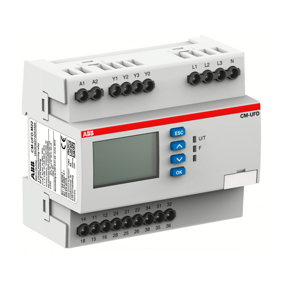
The relay is delivered with default settings in accordance to CEI
0-21 table 8. Thanks to the wide backlit display and to appropriate
buttons all relay parameters can be easily set. The userfriendly
menu structure starts with the main page that shows the real time
measured values. Using the arrow keys the device offers the
possibility to switch between the real time voltages and the 10
minutes average voltages
Menu navigation:
-Press OK button to enter the menu
-Press arrow buttons to move between functions and parameters
-Press OK button to enter the chosen page
-Press arrow buttons to modify the values of the parameters
-Press OK button to confirm the value and proceed
-Press ESC button to return to the previous menu.
Changes to parameters are always possible to cancel by pressing
the ESC button. Visualization of the parameter is always possible,
modification only after having entered the password.
6
