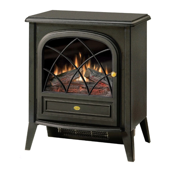
Dimplex ELECTRALOG CS3311 Руководство по эксплуатации - Страница 6
Просмотреть онлайн или скачать pdf Руководство по эксплуатации для Плита Dimplex ELECTRALOG CS3311. Dimplex ELECTRALOG CS3311 13 страниц. Compact stove
Также для Dimplex ELECTRALOG CS3311: Руководство пользователя (14 страниц), Руководство по эксплуатации (11 страниц), Руководство по эксплуатации и техническому обслуживанию (12 страниц), Руководство по эксплуатации (13 страниц)

Light Bulb Replacement
Allow at least five (5) minutes for light bulbs to cool before
touching bulbs to avoid accidental burning of skin.
Light bulbs need to be replaced when you notice a dark
section of the flame. There are two (2) bulbs under the log
set which generate the flames and embers.
Disconnect power before attempting any maintenance or
cleaning to reduce the risk of electric shock or damage to
persons.
Helpful Hints
It is a good idea to replace all light bulbs at one time if they
are close to the end of their rated life. Group replacement
will reduce the number of times you need to open the unit to
replace light bulbs.
Lower Light Bulb Requirements
Quantity of two (2) clear chandelier or candelabra bulbs with
an E-12 (small) socket base, 25 Watt rating.
Do not exceed 25 Watts per bulb
To access the light bulb area (Figure 3):
1. Remove the five (5) Phillips screws on the access panel
at the rear of the stove and remove.
2. Examine the bulbs to determine which bulbs require
replacement.
3. Hold the socket while unscrewing the bulb.
4. Hold the socket while screwing in the new bulb.
5. Reattach Access Panel with screws removed in step 1.
Figure 3
Access Panel
Light Bulbs (2)
Screws (5)
6
Partially Reflective Glass Replacement
If the stove was operating prior to servicing allow at least
10 minutes for light bulbs and heating element to cool off to
avoid accidental burning of skin.
Disconnect power before attempting any maintenance or
cleaning to reduce the risk of electric shock or damage to
persons.
Replacement Procedure
1. Open stove door.
2. Remove the 11 Philips screws that attach the top panel
to the stove as shown in Figure 4. There are: four (4)
screws along each side; and three (3) screws at the front,
accessible behind the door.
3. Remove top panel.
4. Slide partially reflective glass up from within the stove to
remove.
5. Properly orient replacement partially reflective glass and
slide it down into place.
6. Position top panel back onto stove and screw into place
with 11 screws removed in step 1.
Figure 4
Partially
Reflective
Glass
Switch Replacement
If the stove was operating prior to servicing allow at least
10 minutes for light bulbs and heating element to cool off to
avoid accidental burning of skin.
Disconnect power before attempting any maintenance or
cleaning to reduce the risk of electric shock or damage to
persons.
Replacement Procedure:
1. Open stove door.
Top Panel
Screws (11)
