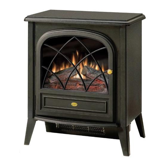
Dimplex ELECTRALOG CS4416 Руководство по эксплуатации - Страница 9
Просмотреть онлайн или скачать pdf Руководство по эксплуатации для Плита Dimplex ELECTRALOG CS4416. Dimplex ELECTRALOG CS4416 11 страниц. Compact stove
Также для Dimplex ELECTRALOG CS4416: Руководство пользователя (14 страниц), Руководство по эксплуатации (13 страниц), Руководство по эксплуатации (13 страниц)

- 1. Table of Contents
- 2. Operation
- 3. Replacement Parts List
- 4. Exploded Parts Diagram
- 5. Wiring Diagram
- 6. Light Bulb Replacement
- 7. Mirror Replacement
- 8. Switch Replacement
- 9. Flicker Motor/Flicker Rod Replacement
- 10. Remote Control Replacement
- 11. Heater Assembly/Cutout Replacement
- 12. Thermostat Replacement
- 13. Power Cord Replacement
Heater Assembly/Cutout Replacement
If the stove was operating prior to servicing allow at least
10 minutes for light bulbs and heating element to cool off to
avoid accidental burning of skin.
Disconnect power before attempting any maintenance or
cleaning to reduce the risk of electric shock or damage to
persons.
Replacement Procedure
1. Turn stove onto its back.
2. Remove four (4) Philips screws as shown in Figure 7
(page 7) to release the bottom pan.
CAUTION: Use caution when removing the bottom pan
as the Heater Assembly is attached to it and is wired to
the stove.
4. Locate the Heater Assembly in the center of the bottom
panel (Figure 11).
Figure 11
Heater
Assembly
Cutout
5. Remove the one (1) small Phillips screw holding the
Cutout in place on the Heater Assembly (Figure 11).
Cutout Replacement:
i.
Open stove door.
ii. Remove the 11 Philips screws that attach the top panel to
the stove as shown in Figure 4 (page 6). There are: four
(4) screws along each side; and three (3) screws at the
front, accessible behind the door.
iii. Remove top panel.
iv. Slide mirror up from within the stove to remove
v. Disconnect the two (2) yellow wire clips of the freed
Cutout. The shorter wire connects to the front terminal
of the Element (Figure 12). The longer wire runs through
Figure 12
Short yellow to front
terminal of Element
vi. Discard old Cutout
vii. Feed longer yellow (or other color) wire through stove
To Terminal Block
viii. Connect shorter yellow (or other color) wire from
ix. If Heater Assembly is not to be replaced, attach Cutout
Heater Assembly Replacement (Continued):
6. Disconnect the seven (7) wire clips from the Heater
7. With the Heater Assembly and Bottom Pan free from the
Figure 13
9
the stove and connects to Heater ON/OFF Switch.
Cutout
Short yellow looped to
element terminals
Blue from lower
terminal of Element
to Thermostat
from replacement Cutout to the left terminal of the Heater
ON/OFF Switch (middle of switch).
replacement Cutout to front terminal of Heater Element
(Figure 12).
to Heater Assembly using screw removed in step 5 and
reassemble stove following steps 1 through 4 in reverse
order.
Assembly, noting their original locations.
chassis of the stove, remove the four (4) Philips screws
that hold the Heater Assembly in place from the bottom
surface of the pan (Figure 13).
Screws to remove (4)
Long yellow to Heater
ON/OFF Switch
Short yellow from
rear element
terminal to right
motor terminal
Blue from left
terminal of motor to
Terminal Block
