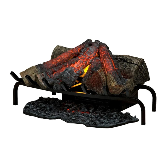
Dimplex DLG1058 Руководство по эксплуатации - Страница 7
Просмотреть онлайн или скачать pdf Руководство по эксплуатации для Электрический нагреватель Dimplex DLG1058. Dimplex DLG1058 11 страниц. Dimplex
Также для Dimplex DLG1058: Руководство пользователя (18 страниц), Руководство по устранению неполадок (2 страниц)

POWER CORD REPLACEMENT
Tools Required: Philips head screwdriver
Needle-nose pliers
Flat Head Screwdriver
WARNING: If the log grate was operating prior to ser-
vicing, allow at least 10 minutes for light bulbs and heating
elements to cool off to avoid accidental burning of skin.
WARNING: Disconnect power before attempting any
maintenance to reduce the risk of electric shock or damage
to persons.
1.
Disconnect and remove all of the logs from the unit and
put them in a safe place.
2.
Remove the two (2) screws that secure the flicker mo-
tor onto the bracket. (Figure 3)
3.
There are four (4) screws that secure the bottom as-
sembly to the grate. Remove the four (4) screws and
the whole box can be removed and enable you to have
easier access to everything. (Figure 4)
4.
Remove the two (2) screws on the top panel and the
six (6) screws on the back panel (Figure 5). This will
allow the housing to open to access the internal com-
ponents.
!
NOTE: The whole assembly can be opened at this
point, ensure that there is no strain added to any of the wir-
ing within the housing, when the two halves are separated.
5.
Follow the wiring from the power cord up to the remote
control receiver board, removing any tie wraps and
remove the connections, taking note of the original
locations.
Figure 3
Figure 4
Figure 5
!
NOTE: Use a flat head screwdriver to gently pry
between the end of the connector and the remote control
receiver to release the wires.
6.
With needle nosed pliers, squeeze and push the grom-
met securing the power cord out of the casing.
7.
Insert the new power cord and grommet, reattaching
the wire with new tie wraps.
8.
Reconnect the wires according in their original configu-
ration.
9.
Re-assemble the remainder of the log grate in reverse
order from the instructions above.
HEATER ASSEMbLY REPLACEMENT
Tools Required: Philips head screwdriver
Flat Head Screwdriver
WARNING: If the log grate was operating prior to ser-
vicing, allow at least 10 minutes for light bulbs and heating
elements to cool off to avoid accidental burning of skin.
WARNING: Disconnect power before attempting any
maintenance to reduce the risk of electric shock or damage
to persons.
1.
Disconnect and remove all of the logs from the unit and
put them in a safe place.
2.
Remove the two (2) screws that secure the flicker mo-
tor onto the bracket. (Figure 3)
3.
There are four (4) screws that secure the bottom as-
sembly to the grate. Remove the four (4) screws and
the whole box can be removed and enable you to have
easier access to everything. (Figure 4)
4.
Remove the two (2) screws on the top panel and the
six (6) screws on the back panel (Figure 5). This will
allow the housing to open to access the internal com-
ponents.
5.
Remove the four (4) screws that secure the heater to
the housing. (Figure 6)
!
NOTE: The whole assembly can be opened at this
point, ensure that there is no strain added to any of the wir-
ing within the housing, when the two halves are separated.
7
