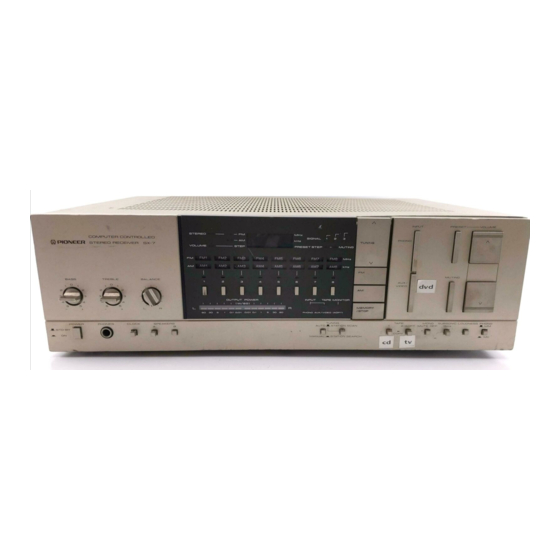
Pioneer SX-7 Руководство по эксплуатации - Страница 13
Просмотреть онлайн или скачать pdf Руководство по эксплуатации для Приемник Pioneer SX-7. Pioneer SX-7 15 страниц. Computer controlled stereo receiver

4. Loudness as determined by a twin T-shaped
filter connected between pin 3 (6) and pin 5
(14) is activated when the LOUD terminal
(pin 7) is switched to L level.
The operation command input key matrix for
the VOLUME control is outlined in Fig. 1-7.
Key description
VOLUME UP, DOWN : Increase and decrease of
5-bit electronic volume control
data
(*11). 32 positions are available (00 to
3 1 ) .
MUTING : Audio muting switch (*12).
VOLUME PRESET : Memory switch for the elec-
tronic volume control steps positions
(32 positions from 00 to 31).
MEMORY/STOP
: Memory store enable key. A
single push enables VOLUME position
and STATION frequency to be stored
in memory during a 5 second period.
(*11)
The S-bit output data from Oa - OZ and Rgpins is
conuerted f'rom digital to analog data by ladder
resistor and applied to pin 12 of PA5004.
(*12)
The Rg pin is switched alternately to H and L leuels
each time this switch is pressed. This H/L leuel is
applied to pin 11 of PA50O4, the L leuel resulting in
actiuation of the muting circuit.
o Other Terminals
R4
Switched to L level when the electronic
volume control position (00 - 31) is display-
ed. The VOLUME indicator is controlled by
this signal (SX-? and SX-6).
Switched to L level when the VOLUME
PRESET key is pressed once, and when the
MEMORY/STOP key is pressed, L level and
H level are switched alternately for a 5
second period. The PRESET STEP indicator
is controlled by this signal.
Switched to L and H level alternately each
time the MUTING
key is pressed. The
PA5004 audio muting operation (-25dB)
and the MUTING indicator are both con-
trolled by this signal.
Switched to L level during time display by
PD6007. The colon (:) in the time display is
controlled by this signal (SX-7).
And with the PD6004, this pin is switched
to L and H levels alternately during frequen-
cy scanning operations, the signal being used
to turn the TUNED indicator on and off
(Sx-5 and SX-4).
R5
: Switched to
L level when 50kHz unit
included in the FM tuning frequency (during
tuning mode where FM frequencies are
changed in 50kHz steps). This signal controls
the "0" and "5" in the 5th digit position
(10kHz unit) in the FM frequency display.
And with the PD6004, this pin is switched
to L level when the LW band is selected (in
models equipped with
2-band AM tuner
section).
R6
: Synthesizer IC (M54922P) control output
(data transfer clock I). Data transfer is
commenced by the trailing edge of this
signal (i.e. the moment that the pin is
switched to L level).
R7
: Synthesizer IC (M54922P) control output
(data transfer clock II). Data reading timing
signal. The M54922P reads data by synchro-
nizing with the trailing edge of this signal.
R8, R9, R10, R11 : Data output and key inputs
applied toM54922P.
RL2 : Muting output. Switched to L level for
about 1 second when PHONO, AUX, FM
and AM (LW/MW) key is pressed. Also
switched to L level (for about 0.7 seconds)
when the Ml
to
M8, TUNING
UP or
TUNING
DOWN key is pressed. These
signals control the electronic switching IC
(PA4008) in order to suppress switching
noise.
Rl-3 : Scanning operation stopped when an H level
input signal is applied during STATION
SCAN or STATION SEARCH tuning mode.
Input of detector signal from tuner section
tuning detector circuit.
Memory Hold
Model SX-7 is equipped with an auxiliary power
supply circuit used to supply the microcomputer
with power irrespective of the POWER switch
position. In this way, the microcomputer RWM
(read write memory) contents can be preserved
for about 2 weeks when the AC mains power is
completely switched off. The clock function is
inhibited in this case. If the AC mains power is
left off for more lhan 2 weeks, the RWM contents
will disappear, and will therefore have to be
rewritten if the memory is to be used again.
The RWM hold period in the SX-6, SX-5 and
SX-4 models when the POWER switch is left off
is about 3 days. When two new size "AA"
dry
batteries are used, however, memory contents can
be maintained for several vears.
R1
R 2
R3
