Pioneer A-407R Руководство по эксплуатации - Страница 14
Просмотреть онлайн или скачать pdf Руководство по эксплуатации для Усилитель Pioneer A-407R. Pioneer A-407R 29 страниц. Stereo amplifier
Также для Pioneer A-407R: Руководство по эксплуатации (12 страниц)
- 1. Table of Contents
- 2. Safety Information
- 3. Exploded Views and Parts List
- 4. Schematic Diagram
- 5. Pcb Connection Diagram
- 6. Pcb Parts List
- 7. Adjustment
- 8. General Information
- 8. IC Information
- 8. Block Diagram
- 9. Panel Facilities and Specifications
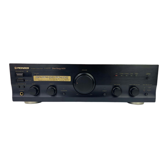
- 9. Front Panel
- 9. Remote Control
- 9. Specifications
1
A-407R
4. PCB CONNECTION DIAGRAM
4.1 AF ASSY
A
POWER
TRANSFORMER
T1
B
NOTE FOR PCB DIAGRAMS:
1. Part numbers in PCB diagrams match those in the schematic
diagrams.
2. A comparison between the main parts of PCB and schematic
diagrams is shown below.
Symbol in PCB
Symbol in Schematic
Diagrams
Diagrams
B
C
E
B C E
B
C
E B
B C E
D
G S
D
G
S
G
D
S
S
D
G
C
1
3
2
S
G
3. The parts mounted on this PCB include all necessary parts
for several destination.
For further information for respective destinations, be sure
to check with the schematic diagram.
4. Viewpoint of PCB diagrams
Capacitor
Connector
Chip Part
P.C.Board
D
SIDE A
A
14
1
2
A
AF ASSY
E
CN803
Part Name
B
C
E
Transistor
C
E
Transistor
with resistor
D
G S
Field effect
transistor
G
D
S
MOS
Field effect
transistor
Resistor array
3-terminal
regulator
SIDE A
SIDE B
C
CN501
F
J5
2
3
3
4
4