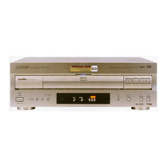
Pioneer DVL-919E Руководство по эксплуатации - Страница 2
Просмотреть онлайн или скачать pdf Руководство по эксплуатации для DVD-плеер Pioneer DVL-919E. Pioneer DVL-919E 11 страниц. Dvd ld player dvl-919e

DVL-919E
1. CONTRAST OF MISCELLANEOUS PARTS
NOTES : ÷ Parts marked by " NSP " are generally unavailable because they are not in our Master Spare Parts List.
÷ The
mark found on some component parts indicates the importance of the safety factor of the part.
Therefore, when replacing, be sure to use parts of identical designation.
÷ Reference Nos. indicate the pages and Nos. in the service manual for the base model.
÷ When ordering resistors, first convert resistance values into code form as shown in the following examples.
Ex. 1
When there are 2 effective digits (any digit apart from 0), such as 560 ohm and 47k ohm (tolerance is shown by
J = 5%, and K = 10%).
= 56 10
560
= 47 10
47k
= R50 ...................................................................... RN2H Â 5 0 K
0.5
= 1R0 ......................................................................... RS1P 1 Â 0 K
1
Ex. 2
When there are 3 effective digits (such as in high precision metal film resistors).
5.62k
7 CONTRAST TABLE
DVL-919E/WY, WY/RD, WY/RE and DVL-909/WY are constructed the same except for the following:
Ref. No. Mark
Symbol and Description
PCB ASSEMBLIES
NSP
CLDGM ASSY
P9 - 13
CLDM ASSY
P7 - 21
JCKB ASSY
P7 - 26
MSWB ASSY
DVDM ASSY
PACKING
P3 - 6
Remote Control Unit (CU-DV013)
P3 - 6
Remote Control Unit (CU-DV029)
P3 - 9
Operating Instructions
(English/French/German/Italian)
P3 - 10
Operating Instructions
(Spanish/Portuguese/Dutch/Swedish)
P3 - 11
NSP
Warranty Card
P3 - 15
Packing Case
P3 - 16
Label
P3 - 17
Label (Region)
FRONT PANEL SECTION
P5 - 1
Front Almi
P5 - 18
Name Plate
TOP VIEW SECTION
P7 - 9
Heat Sink
P7 - 10
Radiation Seat
BOTTOM VIEW SECTION
P9 - 29
Rear Cover
P9 - 35
Housing Assy (13P)
P9 - 39
Label (Region)
1 : Refer to " PCB PARTS LIST ", " 2. SCHEMATIC DIAGRAM " and " 3. PCB CONNECTION DIAGRAM ".
2 : Although VWV1639 and VWV1578 are differnt in part number, they have same service parts.
3 : Although VWG2017 and VWG1895 are differnt in part number, they have same service parts.
4 : Refer to " CONTRAST OF PCB ASSEMBLIES ".
2
= 561 ................................................... RD1/4PU 5 6 1 J
1
= 473 .................................................. RD1/4PU 4 7 3 J
3
= 562 10
= 5621 ........................................... RN1/4PC 5 6 2 1 F
1
DVL-909
VWM1806
VWS1332
VWV1578
VWG1895
VWS1328
VXX2534
Not used
VRE1069
VRF1043
ARY7008
VHG1724
Not used
VRW1701
VAH1280
VAM1051
VNE2134
VEB1282
VNA1925
VKP2162
VRW1700
Part No.
WY
WY
VWM1886
VWS1365
VWV1639
VWG2017
VWS1373
Not used
VXX2608
VRE1076
VRF1047
ARY7022
VHG1769
Not used
VRW1701
VAH1304
PAN1377
Not used
Not used
VNA2030
VKP2199
Not used
DVL-919E
WY/RD
WY/RE
VWM1886
VWM1886
VWS1365
VWS1365
VWV1639
VWV1639
VWG2017
VWG2017
VWS1373
VWS1373
Not used
Not used
VXX2608
VXX2608
VRE1076
VRE1076
Not used
Not used
Not used
ARY7022
VHG1769
VHG1769
VRW1761
VRW1756
VRW1705
VRW1755
VAH1304
VAH1304
PAN1377
PAN1377
Not used
Not used
Not used
Not used
VNA2052
VNA2052
VKP2199
VKP2199
VRW1704
VRW1754
Remarks
1
2
3
4
