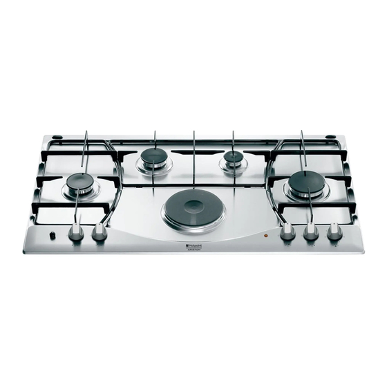
Ariston PH 941MSTB Руководство по установке и использованию - Страница 18
Просмотреть онлайн или скачать pdf Руководство по установке и использованию для Варочная панель Ariston PH 941MSTB. Ariston PH 941MSTB 34 страницы. Built-in cooking table
Также для Ariston PH 941MSTB: Инструкция по установке и использованию (13 страниц), Руководство по эксплуатации (13 страниц), Руководство по эксплуатации (20 страниц)

- 1. Visto da Vicino
- 2. Come Utilizzarlo
- 3. Close-Up View
- 4. How to Use Your Appliance
- 5. Practical Advice
- 6. Is There a Problem
- 7. Safety Is a Good Habit to Get into
- 8. Installation Instructions for Built-In
- 9. Burners and Nozzle Specifications
- 10. Comment L'utiliser
- 11. Conseils D'utilisation
- 12. Caractéristiques des Brûleurs Et des Injecteurs
The following instructions are directed at the qualified
installer so that the installation and maintenance
proceedures may be followed in the most professional and
expert manner possible. Important: Unplug the electrical
connection before performing any maintenance or
regulation upkeep work.
Positioning for gas hob
Important: this unit may be installed and used only in
permanently ventilated rooms according to the British
Stancards Codes Of Practice: B.S. 6172 / B.S. 5440, Par.
2 and B.S. 6891 Current Editions. The following
requirements must be observed:
a) The room must be fitted with a ventilation system which
vents smoke and gases from combustion to the outside.
This must be done by means of a hood or electric
ventilator that turns on automatically each time the hood
is operated.
In a chimney stack or branched flue.
(exclusively for cooking appliances)
b) The room must also allow for the influx of the air needed
for proper combustion. The flow of air for combustion
purposes must not be less than 2 m
capacity. The supply of said air can be effected by means
of direct influx from the outside through a duct with a
inner cross section of at least 100 cm² which must not be
able to be accidentally blocked. Those appliances which
are not fitted with a safety device to prevent the flame
from accidentally going out must have a ventilation
opening twice the size otherwise required, i.e. a minimum
of 200cm
2
(Fig. A). Otherwise, the room can be vented
indirectly through adjacent rooms fitted with ventilation
ducts to the outside as described above, as long as the
adjacent rooms are not shared areas, bedrooms or
present the risk of fire (Fig. B).
Detail A
A
Examples of ventilation holes
for comburant air.
Fig. A
Installation Instructions for built-in
Directly to the Outside
3
/h per kW of installed
Adjacent
Room to be
Room
Vented
Enlarging the ventilation slot
between window and floor.
Fig. B
c) Intensive and prolonged use of the appliance may ne-
cessitate supplemental ventilation, e.g. opening a window
or increasing the power of the air intake system (if present).
d) Liquidified petroleum gases are heavier than air and, as
a result, settle downwards. Rooms in which LPG tanks
are installed must be fitted with ventilation openings to
the outside in order to allow the gas to escape in the
event of a leak. Therefore, LPG tanks, whether empty or
partially full, must not be installed or stored in rooms or
spaces below ground level (cellars, ect.). It is also a good
idea to keep only the tank currently being used in the
room, making sure that it is not near sources of heat
(ovens, fireplaces, stoves, etc.) that could raise the internal
temperature of the tank above 50°C.
Installation of built-in stove tops
The gas hobs are prepared with protection degree against
excessive heating of type X, the appliance can therefore
be installed next to cabinets, provided the height does not
exceed that of the hob. For a correct installation of the
cooking hob the following precautions must be followed:
a) The hob may be located in a kitchen, a kitonen/diner
or bed sitting room, but not in a bathroom or shower
room.
b) The furniture standing next to the unit, that is higher
than the working boards, must be placed at least
110mm from the edge of the board.
c) The cabinets should be positioned next to the hood at
a height of at least 420 mm (Fig. C).
d) Should the hob be installed directly under a cupboard,
the letter should be at least 700mm (millimetres) from
the worktop, as shown in Fig. C.
e) The dimensions of the room for the furniture must be
those indicated in the figures in the last two pages of
the cover. Fixing hooks are provided which allow to
place the hob plate on work tops that measure from
20 to 40 mm in thickness (see Fig. D). To obtain a good
fixing of the hob plate it is advisable to use all the hooks
supplied.
min. 55 mm.
18
HOOD
900
Min.
mm.
Fig. C
835 mm.
Fig. D
