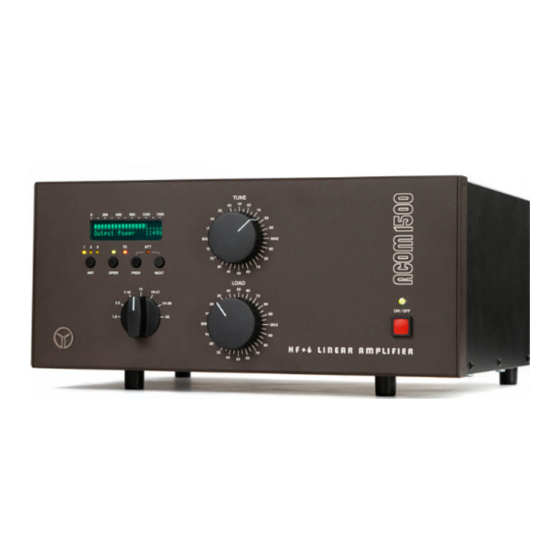
Acom 1500 Руководство по замене
Просмотреть онлайн или скачать pdf Руководство по замене для Усилитель Acom 1500. Acom 1500 9 страниц. Tube replacement

This step-by-step instruction is about the tube replacement and idling currents
re-adjustment of ACOM1500 power amplifier. Please follow all details closely since
the work is difficult, with many details to keep track about, and might be
dangerous too. Do not hesitate to contact your local dealer or nearest ACOM's
service for any advice. Please don't attempt tube replacement by yourself, if you
don't feel comfortable with repairs!
SAFETY FIRST!
W A R N I N G
===========================
The amplifier works with high voltages up to
safety pull the amplifier power plug out of the mains wall outlet and WAIT AT
LEAST 30minutes EACH TIME BEFORE you remove the cover of the amplifier. Disconnect
all cables from the amplifier (grounding last). Do not touch any part inside while
the amplifier is open because some residual voltages may still be present!
1. Removing the top cover.
Using a Philips-2 screwdriver, unscrew 9 pcs of "eco-fix" flange-button head
screws to release the top cover (2x3 pcs on each bottom-side edge, and three more
on the rear-top edge of the box).
Lift the rear edge of the cover slightly (to 2-3cm) and then pull the cover
backwards, in order to release it from front-panel's chutes. Remove the top cover.
2. Discharging HV capacitors.
You will see inside:
- the MAINS PCB that is mounted on an aluminum sub-chassis, just above the big HV
transformer;
- the HV rectifier PCB in front of the MAINS PCB (with four big diodes, one wire-
wound resistor, and one disc ceramic capacitor on it);
- the HV filter PCB, located just below the HV rectifier (with 8 electrolytic
capacitors on it).
ACOM1500 TUBE REPLACEMENT
3000V
which
is LETHAL!
For your
1
