ABB EBN861 Инструкция - Страница 10
Просмотреть онлайн или скачать pdf Инструкция для Блок управления ABB EBN861. ABB EBN861 18 страниц. Power electronic units for field installation. for the control of contrac actuators of the pme, lme, rhd or rsd series
Также для ABB EBN861: Руководство по эксплуатации (17 страниц)

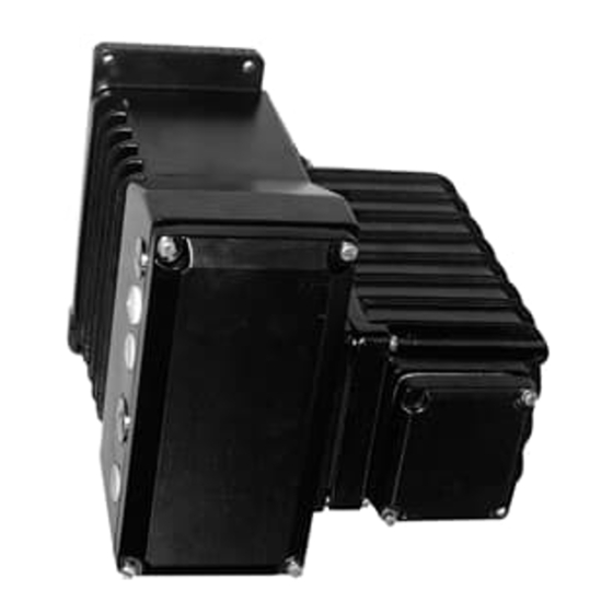
8.2.1 EBN861
Electronic unit EBN861 has a total weight of around 42 kg. For safety reasons it may be necessary to
mount each of the two parts separately.
- Undo and remove the cover screws.
- Fold down the front part, then lift it off from the hinge bolts towards the top.
- Undo the internal connection between the two housing parts.
- Undo the hinge screw
- First mount the rear part of the housing
- Attach the front housing part to the hinge bolts, insert a screw into the top bolt and fasten.
- Make the internal connections between the two housing parts.
- Close the cover and fasten the cover screws
- Connect the cables
9.
Electrical connection
Each actuator requires a Contrac electronic unit which is loaded with the type specific-software. Care-
fully consider the instructions for the electronic unit and compare the data labels of the actuator and
the electronic unit in order to ensure a proper hard- and software assignment.
The cable between the actuator and the electronic unit is connected to terminals. Consider the follow-
ing issues:
- Consider the local regulation concerning the setup of electrical devices within hazardous areas. This
applies particularly to EN 60079-14 for the setup of the screen and the potential compensation be-
tween the actuator, the electronic unit and the motor protection unit (refer 1) to fig. 8 and 9).
- For the connection of the motor and the position transmitter only use ATEX certified EEx e cable
glands with IP66 acc. to EN 50019.
- Use a cable socket or a solid wire, bended to a „U", to connect the motor cable.
- Ensure a proper strain relief for all cable connections.
- Protect all cables in the connections chambers against contact with metal components. Ensure a
gap of at least 6 mm between all conductive components.
- Remove the desiccant in motor and position sensor.
- Do not change the factory-set position of the motor terminal chamber.
- Seal all not used cable entries with ATEX certified IP66 plugs.
- Use a certified cut-off unit for the thermal motor monitoring. Permitted units are e. g.:
type 3RN1, ident no. II (2) G, PTB 01 ATEX 3218 , Siemens or
type EMT6-..., ident no. II (2) G, PTB 02 ATEX 3162 , Moeller
The ABB motor temperature monitoring unit SD241B may also be used for these measures.
For details see instructions for electronic units for rack installation.
10
