FirePro 08451 Руководство - Страница 5
Просмотреть онлайн или скачать pdf Руководство для Панель управления FirePro 08451. FirePro 08451 20 страниц. Fire control panel
Также для FirePro 08451: Краткое руководство по эксплуатации (3 страниц)

Circuit 1 Alarm Output
3.5
The Circuit 1 Alarm Output is a zoned detection circuit capable of operating up to 30
conventional detectors, 100 metres of linear heat detection cable or 30 manual actuators.
The Circuit 1 Alarm Output can be programmed for detection and alarm, or for automatic
discharge if an alarm is detected on this circuit.
The supplied end-of-line resistor (22k or 27kΩ) must be installed on the last detector or manual
actuator in the circuit, or the fire control panel will display a fault. If detection is not used, the
supplied end-of-line plugs (marked green) must be connected.
Circuit 2 Alarm Output
3.6
The Circuit 2 Alarm Output is a zoned detection circuit capable of operating up to 30
conventional detectors, 100 metres of linear heat detection cable or 30 manual actuators.
The Circuit 2 Alarm Output is a detection and alarm circuit only. When in alarm condition the
siren/strobe will operate, however the suppression system will not discharge until manually
operated. The supplied end-of-line resistor (22kΩ) must be installed on the last detector or
manual actuator in the circuit, or the fire control panel will display a fault. If detection is not
used, the supplied end-of-line plugs (marked green) must be connected.
Mounting
3.7
For correct installation, the Fire Control Panel must be mounted by four bolts or screws through
the mounting holes in the flange on both sides of the Module. No penetrations are to be
made through the casing of the panel.
The Fire Control Panel enclosure is rated IP65, so should be installed in a convenient location,
away from where it may be affected by large amounts of water.
It is necessary to complete all wiring and any programming of the detection mode prior to
mounting the panel.
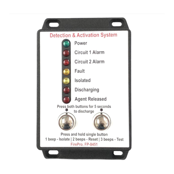
Dimensions and relevant clearances for installing the FP-08451 Control Panel are below. A
Dash Mount Bracket (P/N FP-08451B) is also available and may be used if the minimum
clearances cannot be met.
Fire Detection and Activation System
Model 08451
Rev 3.1
Page | 5
