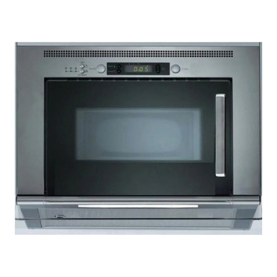
Whirlpool YUMV4084 Руководство по установке - Страница 3
Просмотреть онлайн или скачать pdf Руководство по установке для Вентиляционная вытяжка Whirlpool YUMV4084. Whirlpool YUMV4084 24 страницы. Microwave hood combination
Также для Whirlpool YUMV4084: Руководство по эксплуатации и уходу (15 страниц), Руководство по эксплуатации и уходу (28 страниц)

Parts Supplied
For information on ordering, see "Replacement Parts" section.
A
D
B
E
C
A. L-brackets (2)
G. 16 mm wood screws (10)
B. Rear trim
H. 9.5 mm metal screws (10)
C. Bottom plate
D. Visor
E. Grease filter
K. Washers (2)
F. Damper assembly
L. Hex key
M. Leveling screws (4)
Location Requirements
Check the opening where the microwave oven will be installed.
The location must provide:
Minimum installation dimensions. See "Installation
Dimensions" illustration.
Side cabinets: Support for weight of 75 lbs (34 kg) each,
which includes microwave oven and items placed inside the
microwave oven and side cabinets.
Grounded electrical outlet inside upper cabinet. See
"Electrical Requirements" section.
NOTES:
Installation requires venting above the microwave oven.
Recirculation installation requires venting through a kitchen
soffit. See "Venting Requirements" section. A charcoal filter
kit should be used for recirculation. See "Assistance" section
for information on ordering.
If you are using a rectangular to round transition piece, 3"
(7.6 cm) clearance needs to exist above the damper
assembly so that the damper blade can open freely and fully.
See "Rectangular to Round Transition" illustration in "Venting
Requirements" section.
Some cabinet and building materials are not designed to
withstand the heat produced by the microwave oven for
cooking. Check with your builder or cabinet supplier to make
sure that the materials used will not discolor, delaminate or
sustain other damages.
G
H
I
J
K
L
M
F
I. 16 mm round-head bolts (2)
J. 17 mm shoulder screws (2)
Installation Dimensions
NOTE: The grounded 3 prong outlet must be inside the upper
cabinet. See "Electrical Requirements" section.
⁷⁄₈
23
"
(60.6 cm) min.*
¹⁄₈
24
"
(61.2 cm) max.*
39" (99.1 cm) min.
A. Grounded 3 prong outlet
*Measure from the front edges of the side cabinets.
**For installation with stainless steel filler panel.
NOTE: To avoid stress on the power cord, a minimum of 1¹⁄₂"
(3.8 cm) must exist between the top surface of the microwave
oven's upper component housing and the bottom of the upper
cabinet.
Product Dimensions
20⁷⁄₁₆"
(51.9 cm)
A
21" (53.3 cm) min.
21⁵⁄₈" (54.9 cm)**
11¹⁵⁄₁₆" (30.3 cm) min.
13³⁄₄" (34.9 cm) max.
16¹⁄₈"
(40.9 cm)
3
