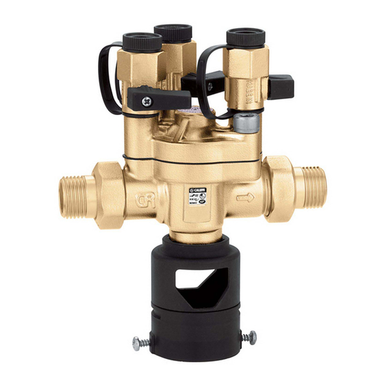
CALEFFI 574 series Руководство - Страница 5
Просмотреть онлайн или скачать pdf Руководство для Сантехническая продукция CALEFFI 574 series. CALEFFI 574 series 16 страниц. Testable, reduced pressure zone backflow preventer
Также для CALEFFI 574 series: Руководство (12 страниц)

De terugstroombeveiliger is opgebouwd uit twee terugslagkleppen (4) en (5),
een kamer die "verminderde-drukzone" (B) wordt genoemd en een hierop
aangesloten afvoerklep (3). Wanneer er water in de terugstroombeveiliging
komt, opent dit de bovenstroomse terugslagklep. Het water drukt tegelijkertijd
via het overstroomkanaal (1) op het membraan (2) dat via de stang de
afvoerklep sluit en dus de benedenstroomse terugslagklep opent. De druk in de
middelste kamer is in normale bedrijfsomstandigheden door een
voorgecalculeerd drukverlies op de eerste terugslagklep altijd minstens
140 mbar (1,4 m w.k.) lager dan de bovenstroomse druk.
Dit drukverschil p tussen de bovenstroomse zone (A) en de middelste zone (B)
is ingelast als veiligheidsmaatregel omdat in geval van beschadiging of
onderdruk de afvoerklep wordt geopend wanneer de bovenstroomse druk nog
minstens 140 mbar hoger is dan de druk in de middelste zone.
Återströmningsskyddet består av två backventiler (4) och (5), en mellanliggande
kammare även kallad den tryckreducerade zonen (B) och en dräneringsventil
(3) ansluten till kammaren. Inkommande vatten öppnar uppströms backventil
och verkar samtidigt, genom kanal (1) på membranet (2) så att
dräneringsventilen stängs. Nedströms backventil öppnar. Trycket i den
mellanliggande kammaren understiger alltid under normal drift trycket
backventilen. Denna tryckskillnad Δp säkerställer att dräneringsventilen öppnar
uppströms med minst 140 mbar (1,4 mvp) på grund av tryckfallet över den första
vid tryckfall uppströms eller fel i systemet nedströms redan när tryckskillnaden
minskat till 140 mbar. Om membranet skadas öppnar säkerhetsfjädern
utloppsventilen och förhindrar vatten att strömma bakåt. Vatten kan således
aldrig strömma från den mellanliggande zonen till zonen uppströms. Om
backventilerna har skador på tätningsytorna märks detta genom att vatten
droppar från dräneringsventilen.
Installazione
Installation
L'installazione del disconnettore deve essere eseguita da parte di personale
Einbauanleitung
qualificato in accordo con la vigente normativa.
Il disconnettore va installato dopo una valvola di intercettazione a monte ed un
Installation
filtro ispezionabile con scarico; a valle va montata un'altra valvola di
Installatie
intercettazione. Il gruppo va installato in una zona accessibile, che abbia
Installation
dimensioni tali da evitare possibili immersioni dovute ad allagamenti accidentali
(vedi schema).
L'apparecchio va installato orizzontalmente. L'imbuto di scarico a norma
EN 1717 deve essere collegato alla tubazione di collegamento alla fognatura.
Prima dell'installazione del disconnettore e del filtro si dovrà effettuare una
pulizia della tubazione mediante un getto d'acqua di grande portata.
Per la protezione della rete pubblica il disconnettore va installato dopo il
contatore dell'acqua, mentre per la protezione delle erogazioni ad uso sanitario
nella rete interna si installa al limite delle zone nelle quali si può verificare un
inquinamento ad esempio: riscaldamenti centralizzati, irrigazione di giardini, ecc.
The installation of backflow preventer should only be carried out by qualified
personnel in accordance with current legislation.
The backflow preventer is installed after an upstream shut-off valve and a
strainer which can be inspected whith a discharge with another shut-off valve
being fitted downstream.
The unit is installed in an accessible area wich is of such a size as to avoid
possible immersions due to accidental flooding (see diagram). The equipment is
installed horizontally. The tundish, complying with the EN 1717 standard, must be
connected to the discharge sewerage. Before installing the backflow preventer
and the strainer the pipe should be cleaned with a high-capacity water jet.
In order to protect the public supply system the backflow preventer is installed
after the water meter and to protect supplies for sanitary purposes in the internal
system it is fitted at the limit of the areas in which contamination can take place
as for example centralized heating systems, garden watering systems etc.
5
