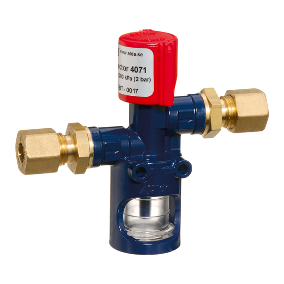
Alde 4071 Руководство по установке - Страница 6
Просмотреть онлайн или скачать pdf Руководство по установке для Аксессуары Alde 4071. Alde 4071 17 страниц. Leak detector

INSTALLATION INSTRUCTIONS FOR LEAK DETECTOR 4071
CE 845 BT-0017
Read through these instructions carefully before installing the leak detector.
The device is intended for control of the soundness of LPG appliances for pressures
up to
2 bar (200 kPa). The leak tester should be connected into the gas system close to the
outlet side of the regulator. This provides a rapid check of each installed appliance
connected after the leak detector. A leak in the system is positively indicated by bub-
bles appearing in the glass sighting chamber. The leak tester may be used as often as
deemed to be necessary.
TECHNICAL SPECIFICATIONS
Appliance type: In-line gas leak detector.
Certified for: Uses in low- or medium-pressure LPG systems operating on butane or
propane up to a maximum pressure of 2.0 bar.
Capacity at low pressure: 355 dm3/h (12.0 kW) at pressure drop of 1 mbar for
butane and 481 dm3/h (12.0 kW) at a pressure drop of 1 mbar for propane.
Capacity at medium pressure: 580 dm3/h (20.0 kW) at pressure up to 2.0 bar for
butane and 790 dm3/h (20.0 kW) for propane.
Note: Difficulty in maintaining outlet pressure of 2.0 bar on butane may be experi-
enced if the temperature is below 15ºC.
Dimensions: Height 93 mm, Depth 30 mm, Width 85 mm, Weight 0.19 kg.
Gas inlet connection: 8 mm or 10 mm coupling suitable for connection of 8 mm or 10
mm copper tube via a nut and olive. The detector inlet is the lower of the 2 connec-
tions.
Gas outlet connection: 8 mm or 10 mm coupling for connection of 8 mm or 10 mm
copper tube via a nut and olive. The detector outlet is the higher of the 2 connections.
IMPORTANT! Naked flame, smoking or embers in the vicinity are absolutely
forbidden.
1. INSTALLATION INSTRUCTIONS
Select the model of leakage detector with suitable connections depending on the
design of the gas supply system. The leak detector shall be fitted after the regulator in
the same space as the gas bottle.
A. Close the main valve on the gas bottle.
B. Mark out the intended location of the leak detector. It shall be mounted in a vertical
position with the sight glass clearly visible. The distance between the detector
and the regulator shall be as short as possible. The direction of flow through the
detector is marked with arrows. It must not be connected so that the gas can pass
in the opposite direction. Carefully fit the detector so that connections, pipes and
detector avoid any damage. Where copper tubes are used supporting sleeves
shall be fitted on the tube. See figure 1.
C. Unscrew the sight glass and add the glycol liquid according to item 3.
D. Secure the detector in position and fit on the gas pipe or copper pipe. When
securely fitting the copper pipe to the leak detector, the innermost nut is to be held
with a spanner (fig 2A) while the outer nut is fastened with another spanner (figure
2B). If this is not done, the nipple can turn round which will result in a leakage at
the connection. The nut must be tightened by 1 ½ turns.
E. Check that the system is leakage proof by carrying out a gas soundness test.
