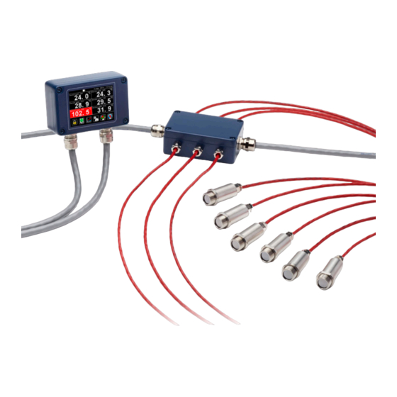
Calex PMB21 Руководство по эксплуатации - Страница 8
Просмотреть онлайн или скачать pdf Руководство по эксплуатации для Аксессуары Calex PMB21. Calex PMB21 17 страниц.

OPERATION
Once the sensor is in position and the power, air, water, and cable connections are secure,
the system is ready for continuous operation by completing the following simple steps:
1
Turn on the power supply
2
Turn on the Modbus Master
3
Read / monitor the temperature
IMPORTANT
BE AWARE OF THE FOLLOWING WHEN USING THE SENSOR:
•
If the sensor is exposed to significant changes in ambient temperature (hot to cold,
or cold to hot), allow 20 minutes for the temperature to stabilise before taking or
recording measurements.
•
Wires must be connected only to the appropriate terminals.
•
Do not damage the cable, as this could provide a path for moisture into the sensor.
•
Do not open the sensor housing. This will damage the sensor and invalidate the
warranty.
MEASURED TEMPERATURES
Average Temperature
The Unfiltered Temperature, averaged over the Average Period
Minimum Temperature
The lowest measured temperature during the Hold Period
Maximum Temperature
The highest measured temperature during the Hold Period
Filtered Temperature
The measured temperature, including Averaging and Hold Processing
Unfiltered Temperature
The "raw" measured temperature without Averaging or Hold Processing
Sensor Temperature
The temperature inside the sensor body - this is usually a few degrees higher than the
ambient temperature.
SETTINGS
Settings can be modified via the PM180 or another Modbus Master.
Emissivity Setting
The emissivity setting should match the emissivity of the target surface. This can be
determined experimentally by comparing measurements with a trusted contact probe, or
estimated using an emissivity table.
Non-reflective non-metals, such as rubber, foods, thick plastics, organic materials and painted
surfaces, generally have a high emissivity, around 0.95. This is the default setting.
Bare, clean metal surfaces can have a very low emissivity, and are often difficult to measure
accurately. If possible, a measurable area of the surface should be painted or coated to
reduce reflections and increase the emissivity.
If the emissivity setting is being updated is being updated continuously by the Modbus
Master, use address 0x17 instead of 0x07 to preserve the sensor's non-volatile memory.
Reflected Energy Compensation & Reflected Temperature
In most applications, the target surface has the same surroundings as the sensor (for
8
