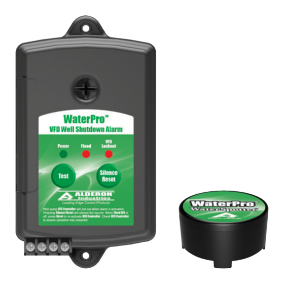
Alderon Industries WaterPro WaterSpotter 8073 Руководство по эксплуатации, техническому обслуживанию и установке - Страница 3
Просмотреть онлайн или скачать pdf Руководство по эксплуатации, техническому обслуживанию и установке для Система безопасности Alderon Industries WaterPro WaterSpotter 8073. Alderon Industries WaterPro WaterSpotter 8073 4 страницы.

WaterPro™ AVFD Series Alarm Panel - Installation Instructions
Installation of the VFD Pressure Transducer to the WaterPro
2. The WaterPro™ Alarm Panel contains a Normally Closed relay for interrupting the transducer signal which is
connected to Terminals 2 and 5 (alarm panel). Terminals 1 and 4 (alarm panel) are internally connected together as
well as Terminals 3 and 6 (alarm panel), which allows for an easy splice connection between the VFD Panel and
the WaterPro™ Alarm Panel (Fig. 9).
3. Connect the Pressure Transducer to the WaterPro™ Alarm Panel. To facilitate the process, assign each color
wire of the pressure sensor to a letter that corresponds to the wiring diagram (Example: Red Wire of the Pressure
Transducer = "A" Wire / Fig. 10). Note: If using a 4-20mA type transducer that contains a shield, make sure to
connect the shield to Terminal 3 and Terminal 6 will be the shield wire returning to the VFD panel.
4. Connect a customer supplied cable (22-18 gauge wire) from the WaterPro™ Alarm Panel Terminals 4, 5 and 6
to the VFD Pressure Transducer Terminal Block (Fig. 10). Note: Transducer "A" wire corresponds with "A*" wire that
connects to the VFD panel and similar to "B" and "C" wires.
5. After the access cover has been removed from the alarm (Fig. 11), use a needle nose pliers (not included) to
remove the desired "break away tabs" from the access cover, lightly pull and twist off tab(s) (Fig. 12). Replace the
access cover and run the wires through the knockouts (Fig. 13).
(Fig. 11)
Alderon Industries • PO Box 827 Hawley, MN 56549 • P: 218-483-3034 • F: 218-483-3036 • alderonind.com
(Fig. 9)
TB6
TB5
TB4
(Fig. 10)
6
5
4 3
2 1
VFD Pressure Transducer
Terminal Block in VFD Panel
(Fig. 12)
Alarm Panel Continued
™
CR1
TB3
TB2
TB1
6
5
4
C*
B*
Transducer Originally Connected
to VFD Panel Terminal Block is
Connected to TB1, TB2 and TB3
of Alarm Panel.
3
2
1
A*
C
B
A
Pressure Transducer
(Fig. 13)
Installation Instructions | Page 3
