Alderon Industries Wireless Versa'larm VA01B Руководство по эксплуатации, техническому обслуживанию и установке - Страница 3
Просмотреть онлайн или скачать pdf Руководство по эксплуатации, техническому обслуживанию и установке для Система безопасности Alderon Industries Wireless Versa'larm VA01B. Alderon Industries Wireless Versa'larm VA01B 6 страниц. 1-zone alarm
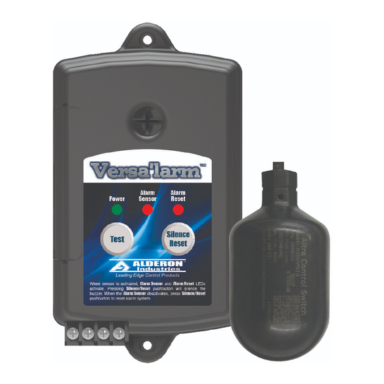
Wireless Versa'larm
1-Zone Alarm - Model VA01B
Part Numbers - 7991 and 7992
Operation, Maintenance and Installation Manual
Installation of the Wireless Transmitter and Float Switch
1. Disconnect all power sources for the wireless transmitter, float
switch, wireless receiver and alarm panel. Unscrew the float
switch (black) from the wireless transmitter (yellow) using the
quick connect/disconnect (Fig. 1).
2. Determine a mounting location for the wireless transmitter. The included mounting kit has a washer, black threaded
locking nut, bolts, and nuts (Fig. 2) which can be used with the threaded post or mounting holes on the transmitter (Fig. 3).
Note: If drilling into a post or bracket using the provided bolts, nuts, and mounting holes in transmitter, a drill with 3/16" bit
and 3/8" wrench are required (not included). The transmitter can also be mounted to a wall or permanent structure with user
provided screws, minimum size of 3" to securely fasten (use plastic anchors if mounting to sheet rock, not included).
3. Mount the float switch, product comes with both a stainless steel pipe
clamp and cast iron cable weight.
a. For pipe clamp models, determine desired activation level (Fig. 4),
then mount the pipe clamp at desired location and tether float switch
cable to approximately four inches.
b. For cable weight models, determine desired activation level (Fig. 5),
then suspend the float switch cable with weight at desired location
and tether cable to approximately six inches.
Note: Wireless Versa'larm™ system (7991 and 7992) is used as a high
level alarm. Alderon normally open float switches activate at 5 degrees
above horizontal and deactivate at 5 degress below horizontal. Check
installation by cyling the float switch on and off to ensure proper operation
for desired activation range after installation is complete.
Alarm Systems
Control Panels
Alderon Industries - Hawley, MN | 218.483.3034 | [email protected] | alderonind.com
(Fig. 2)
Float Switches
Leak Detection Systems
™
(Fig. 3)
(Fig. 4)
Pivot
Point
(Fig. 1)
Mounting Holes
Threaded Post
(Fig. 5)
Pivot
Point
Control
Switch
Pump
Switch
P/N: 101985
Page 3 of 6
Control
Switch
Pump
Switch