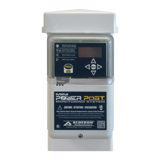
Alderon Industries Mini Power Post MPMS-0001 Руководство - Страница 4
Просмотреть онлайн или скачать pdf Руководство для Измерительные приборы Alderon Industries Mini Power Post MPMS-0001. Alderon Industries Mini Power Post MPMS-0001 4 страницы.

3.0 | Main Menu - Lifetime History
From the LIFETIME HISTORY screen,
press right arrow key to access the menu for
event statistics and then press down arrow
key for the available events within this menu.
3.1
Pump Run Stats
3.2
Extended Pump Run Stats
3.3
High Amp Stats
3.4
Pump Float Stats
3.5
Power Loss Stats
Press right arrow key for the individual stats
of each event type listed above and data
stored in the system. The lifetime statistics
are non-resettable and are displayed in Title
Case format for visual separation from the
resettable statistics, which are displayed
in UPPERCASE format. The non-volatile
memory allows all settings and statistics to
be retained during power outages.
Note: The down arrow key will cycle through
all the lifetime history menu options until a
specific option is selected using the right
arrow key as displayed on the screen. Press
the left arrow key to exit from any screen.
Press the test pushbutton to exit the menu
system.
1
2
7
11
MPMS185B1
1
2 3
4
Mini Power Post
4
Model Number Nomenclature
1
Base Model (Mini Power Post™ Monitoring System)
2
Pump Voltage (120VAC Pump)
5
Included with Product
▪ (1) Mini Power Post™; junction box and cable grips pre-installed on post
▪ (1) Pre-installed, female, 15A, pump power receptacle
(120VAC or 240VAC, voltage depends on model/part number)
▪ (6) Wago connectors
Customer Support
Online
alderonind.com
Email
QR Code
Scan code for full product details
Specifications
Pump Power Receptacle: 120VAC or 240VAC, 15A, 60Hz
Pump Power:
Alarm Power:
Power Consumption:
Enclosure:
Certifications:
FCC Part 15: NOTE: This equipment has been tested and found to comply with the limits for a Class B digital device, pur-
suant to part 15 of the FCC Rules. These limits are designed to provide reasonable protection against harmful interference
in a residential installation. This equipment generates, uses and can radiate radio frequency energy and, if not installed and
used in accordance with the instructions, may cause harmful interference to radio communications. However, there is no
guarantee that interference will not occur in a particular installation. If this equipment does cause harmful interference to
radio or television reception, which can be determined by turning the equipment off and on, the user is encouraged to try
to correct the interference by one or more of the following measures: increase the separation between the equipment and
receiver, connect the equipment into an outlet on a circuit different from that to which the receiver is connected, consult the
dealer or an experienced radio/TV technician for help. Caution: changes / modifications not approved by Alderon Industries
could void the user's authority to operate the equipment.
Monitoring System - Features
™
Power On Indicator - Green LEDs illuminate inside top cover of enclosure cover,
1
power on indicators can be disabled in system settings
Alarm Beacon - Alarm LEDs (various colors) illuminate inside the top cover of
2
enclosure cover
3
Pump Run Indicator - Blue LEDs illuminate inside top cover of enclosure cover, pump
3
run indicators can be disabled in system settings
9
System LED Indicators - Multiple color indicators will illuminate inside top cover of
4
enclosure cover for visual indication of various system events and/or alarm conditions
5
5
OLED Display Screen - Displays system functions in addition to LED indicators
6
Menu Keypad - Toggle for system functions, program settings, and view statistics
6
Test Pushbutton - Quick access to lifetime pump run event counter statistic, test
7
alarm LEDs, or exit the menu system
8
Quick Snap Terminal Block - Connections for system wiring, factory wired
9
Vented Post Cap - Allows airflow, prevents build up of gases/condensation inside post
8
10 QR Code (not shown) - Scan for additional product information (alderonind.com)
11 Cable Grips - Pre-installed for easy installation
Pump Power Receptacle (not shown) - Pre-installed, female, 15A, available in either
12
120VAC or 240VAC (voltage depends on model/part number)
Post - Provides wire routing access for system power and pump power while
13
protecting from water intrusion
13
Alarm Options
(1-Zone Indoor Alarm, 20' Alarm
3
Float, and 20' Filter Switch)
4
Pump Switch Options (15A, 20' Wide Angle)
120VAC or 240VAC, 13A or 15A, 60Hz
(voltage/amps depends on model/part number)
120VAC or 240VAC, 60Hz
(tied in series to pump power)
14 Watts maximum (alarm condition)
Outdoor, rated Type 3R
FCC Part 15 (US/Canada), CSA (US/Canada)
5
Riser Kit/Access Options (2.0" Riser Connection Kit)
