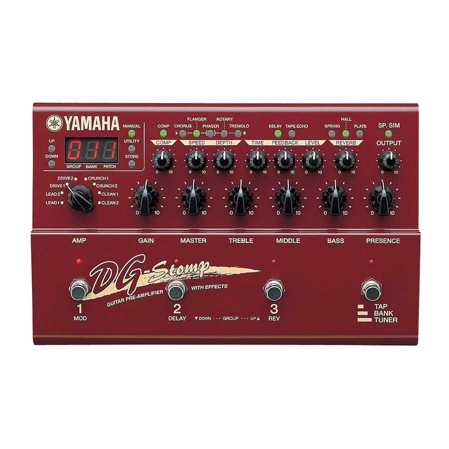
Yamaha DG-Stomp Руководство по эксплуатации - Страница 12
Просмотреть онлайн или скачать pdf Руководство по эксплуатации для Усилитель Yamaha DG-Stomp. Yamaha DG-Stomp 43 страницы. Guitar pre-amplifier with effects
Также для Yamaha DG-Stomp: Дополнительное руководство (1 страниц), Руководство пользователя (32 страниц)

- 1. Specifications
- 2. Panel Layout
- 3. Block Diagram
- 4. Circuit Board Layout
- 5. Wiring
- 6. Disassembly Procedure
- 7. Lsi Pin Description
- 8. IC Block Diagram
- 9. Circuit Boards
- 10. Test Program
- 11. Error Messages
- 12. MIDI Implementation Chart
- 13. Parts List
- 14. Guitar Pre-Amplifier with Effects
- 15. Overall Assembly
- 16. Electrical Parts
DG-Stomp
DISASSEMBLY PROCEDURE
1.
Bottom Case
Remove the six (6) screws marked [30]. The bottom
case can then be removed. (Fig. 1)
2.
DM Circuit Board
2-1.
Remove the bottom case. (See Procedure 1.)
2-2.
Remove the four (4) screws marked [10c-a] and the
five (5) special hexagonal nuts marked [10e] from
the rear panel and the three (3) screws marked [10c-b]
from the DM circuit board. The DM circuit board can
then be removed. (Fig. 2)
Rear
[10c-a]
12
Bottom
[30]: Bind Head Tapping Screw-B 3.0x8 MFZN2BL (EP600190)
[30]
[30]
Fig.1
[10c-a]
Hexagonal Nut
