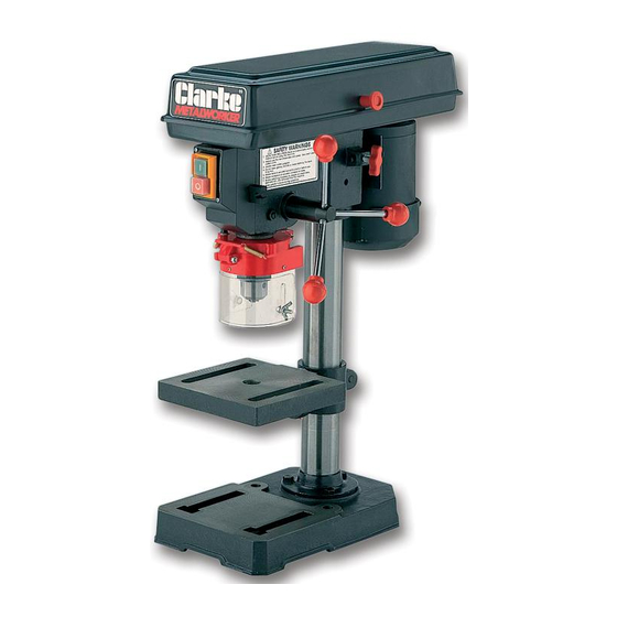
Clarke Metalworker CDP101B Руководство по эксплуатации и техническому обслуживанию - Страница 11
Просмотреть онлайн или скачать pdf Руководство по эксплуатации и техническому обслуживанию для Электроинструмент Clarke Metalworker CDP101B. Clarke Metalworker CDP101B 19 страниц. 13mm drill press

H. Assembling the Depth Stop Assy.
Slide the end of the threaded rod through the bracket
on the side of the head and through the hole in the
Guard Collar. (It may be necessary to turn the collar
slightly to line up the hole). Secure with the nut provided,
from beneath, thereby locking the Depth Stop to the
Guard Collar and hence the Spindle.
(Therefore, as the Spindle is moved downwards, the
depth Stop will move by the same amount).
The pointer may be zeroed by sliding it up or down on its
mounting.
For adjustments, see below.
Fig. 7
SETTINGS and ADJUSTMENTS
Fig. 8
1. Table.
The table may be raised, lowered or swivelled about the
column, by slackening off the table support locking handle,
adjusting accordingly, and re-tightening the handle.
It may also be tilted by loosening the M12 hex. screw, which
secures the table to its' mounting beneath the table, tilting to
the required position and re-tightening the screw.
A scale is provided on the table mounting, measured in
degrees, to assist in setting the required angle (fig.10).
For all normal operations, the table should be set to 0°.
Table Support
Locking Handle
To check to ensure the table is entirely square to the
drill, insert a piece of straight round bar in the chuck,
place a square on the table, and bring it up to the
round bar. Adjust the table tilt if necessary, so that the
table is correctly aligned.
Fig. 10
Fig. 9
Table Tilt Scale
Table shown tilted and swivelled
about the column
11
