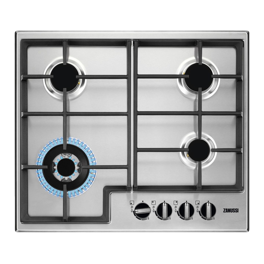
Zanussi Hobs Руководство по эксплуатации и установке - Страница 9
Просмотреть онлайн или скачать pdf Руководство по эксплуатации и установке для Варочная панель Zanussi Hobs. Zanussi Hobs 15 страниц. Gas hobs
Также для Zanussi Hobs: Буклет с инструкциями (12 страниц), Руководство по эксплуатации и установке (7 страниц), Буклет с инструкциями (16 страниц)

ADAPTATION TO DIFFERENT TYPES OF GAS
SUBSTITUTION OF THE
NOZZLES
Remove the grills:
Remove the caps and baffles from the burners:
With a tubular spanner no. 7 unscrew and remove
(fig. 5) the nozzles substituting them with those
corresponding to the type of gas used (see tab):
Remount the parts carrying out the operations
described in reverse. Then substitute the caliber
plate (positioned near the gas supply connection)
with the one corresponding to the new type of
gas. This can be found in the injector bag
supplied.
If the pressure of gas used is different (or
variable) from that foreseen an appropriate
pressure regulator should be installed on the entry
tube.
In case pressure regulators for GPL are used these
should conform to the regulations in force.
REGULATION OF THE
MINIMUM
To regulate the minimum bring the tap to the
minimum flame position.
Extract the knob.
If the tap is of a type with the pin by-pass inside
the bar (Fig. 6-8), it is sufficient to screw or
unscrew according to the type of gas as indicated
in the following paragraph.
If the tap is of a type with a lateral by-pass (Fig.
8) it is necessary to detach the command panel by
applying pressure to the lateral projection (Fig. 7),
then insert a screwdriver through the hole until
the pin is reached.
When transforming from methane gas to GPL gas
fully screw down the by-pass pin.
Finally check that by quickly turning the tap from
the maximum position to the minimum position
the burner is not extinguished; remount the parts
carrying out the operations described in reverse.
The above-described adaption operations can be
easily carried out whatever the positioning or
fixture of the hob to the kitchen unit.
10
FO 0254
TAP
Burner
Auxiliary
Semi-rapid
Rapid
Fig. 5
Fig. 6
Fig. 7
Ø By-pass
of tap
1/100 mm
28
35
45
