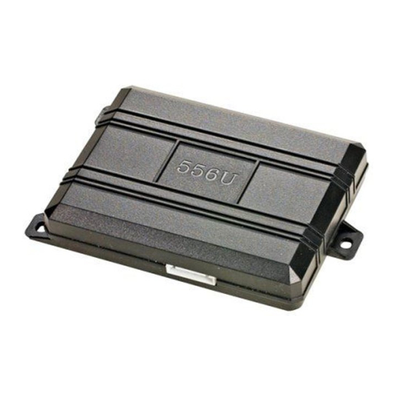
Directed Electronics 556U Руководство - Страница 6
Просмотреть онлайн или скачать pdf Руководство для Автомобильная сигнализация Directed Electronics 556U. Directed Electronics 556U 10 страниц. Immobilizer interface

4. Plug the three-pin connector into the 556U module and cut the 556U's antenna wire off. Discard the antenna
ring.
5. Split open the factory transponder ring tube and cut one of the two wires in half.
6. Connect the factory transponder ring side of the cut wire to the BLACK/WHITE normally closed input wire of
the 556U.
7. Connect the factory transceiver module side of the cut wire to the 556U's BLACK wire.
8. Connect the BLACK/RED wire to the uncut factory transponder ring antenna wire.
9. Plug the 6-pin power plug into the control module.
10 Connect the BLACK wire to chassis ground.
11. Connect the RED wire to a fused source of constant 12V.
12. Connect the BLUE wire to the status output (blue wire) of the remote start system that provides a latched
negative (-) ground while the remote start is active.
13. Test unit before reassembling the steering column.
14. Reassemble the steering column shroud.
© 2004 Directed Electronics, Inc.
6 6
N556U 09/04
